Ultrasound transducer array

a transducer array and ultrasonic technology, applied in the field of ultrasonic transducers, can solve the problems of unwanted energy transmission and reception, destructive and interference of signals transmitted to (or received from) the desired region of spa

Inactive Publication Date: 2005-12-13
QUEENS UNIV OF KINGSTON
View PDF12 Cites 208 Cited by
  • Summary
  • Abstract
  • Description
  • Claims
  • Application Information

AI Technical Summary

Problems solved by technology

The ultrasound energy produced by an array is focused by introducing time delays to the signals delivered to (or received from) individual array elements so that signals transmitted to (or received from) the desired region in space constructively interfere while signals outside this region destructively interfere.
The non-zero amplitude of the radiation pattern away from the peak is caused by imperfect destructive interference and results in transmission and reception of unwanted energy.
Although these techniques work well for arrays designed to operate below 10 MHz, they are not suitable for machining the extemely small and closely spaced elements required for high frequency imaging.
They are also difficult to use with new single crystal relaxor ferroelectric materials such as lead zirconate niobate-lead titanate (PZN-PT) and lead magnesium niobate-lead titanate (PMN-PT) which are brittle and prone to chipping and cracking.

Method used


Image

  • Ultrasound transducer array
  • Ultrasound transducer array
  • Ultrasound transducer array

Examples


example 1

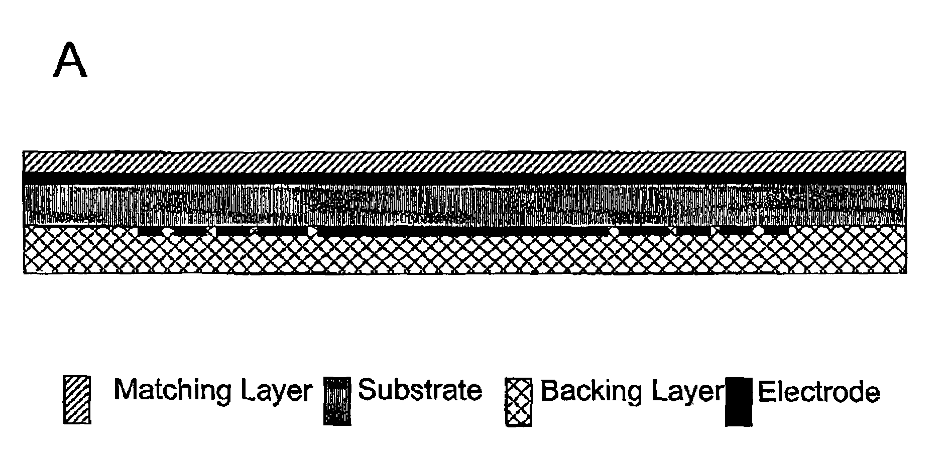
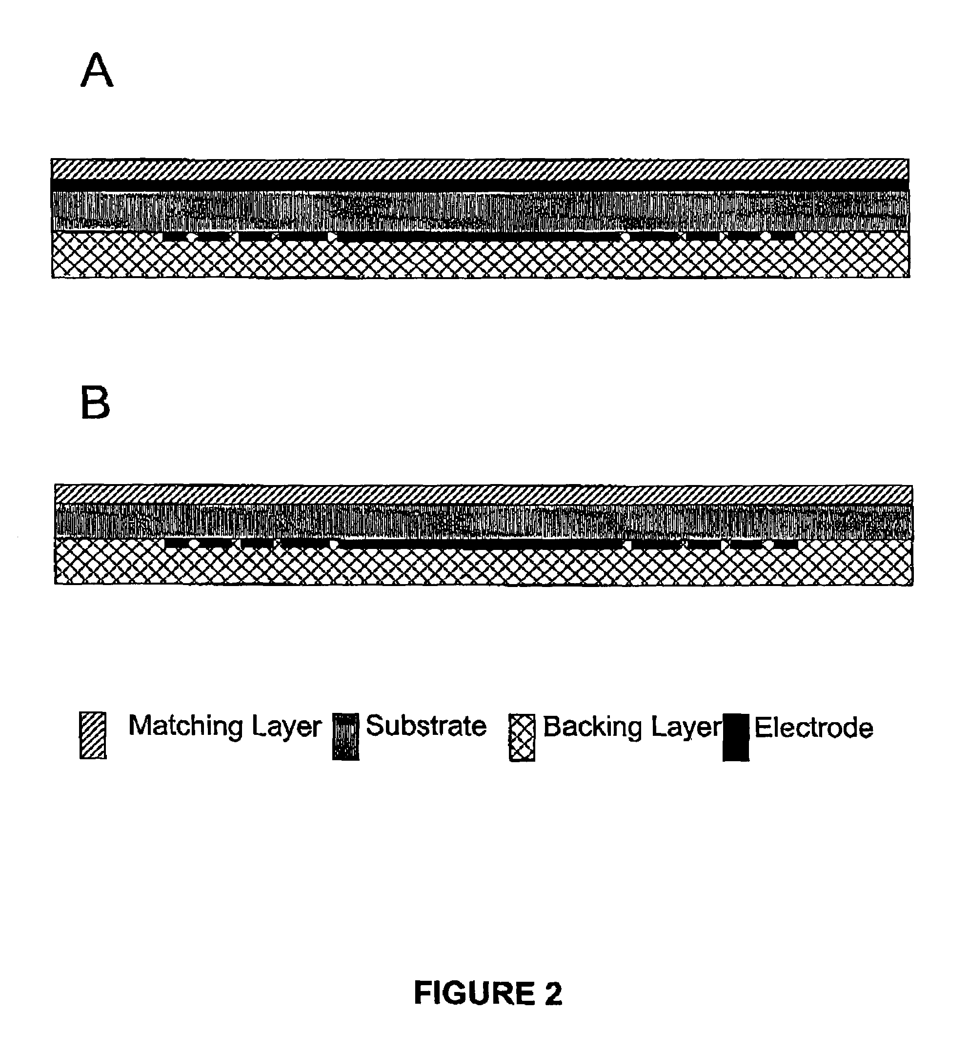
[0051]With reference to FIG. 2B, a high frequency (50 MHz) transducer array comprises a PZT substrate (Motorola 3203HD) having a thickness of approximately 47 μm. An electrode layer of Cr—Au about 1000 Å thick is deposited on the first face of the substrate. An electrode layer of aluminum about 2 μm thick is deposited on the second face. The second face or electrode is patterned using photolithography to define the array geometry as shown in FIG. 3, which figure depicts an electrode pattern suitable for a 50 MHz annular array. A matching layer of silver epoxy at a thickness of approximately 9 μm is applied to the first face of the array. Electrical connections are made to the array elements and a backing layer of tungsten-loaded epoxy (EPO-TEK 301-2), at a thickness of approximately 1 mm, is applied to the second face of the array.

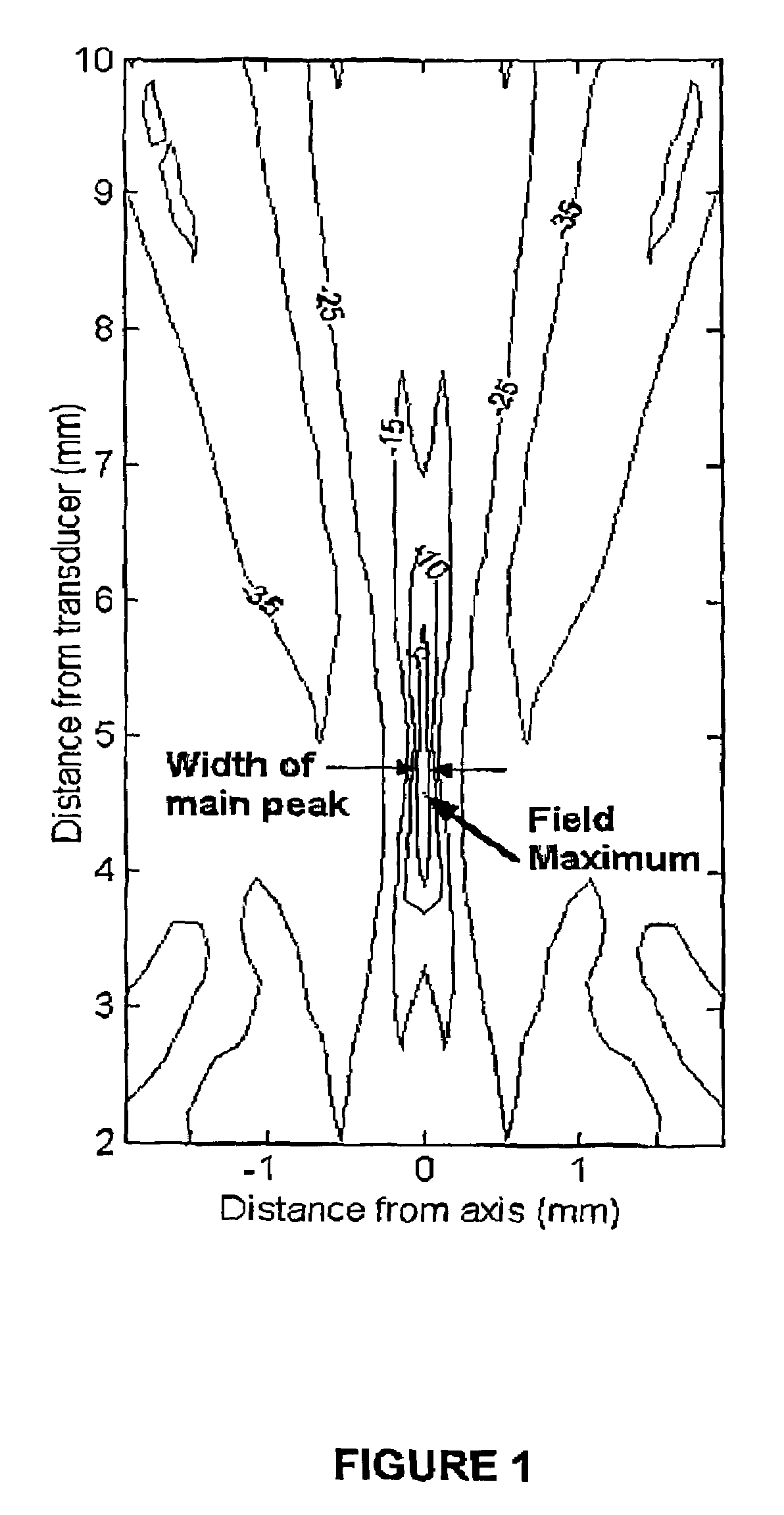
[0052]The performance of several embodiments of a 50 MHz kerfless annular array was evaluated using a finite element model (FEM) (PZFlex, Weidlinger Assoc...

example 2

[0056]The performance of 50 MHz kerfless and sub-diced arrays was evaluated using finite element modeling (PZFlex, Weidlinger Associates, Calif.). Both arrays had 64 elements, 30 μm element spacing, a single front quarter-wavelength matching layer, and a high loss, high impedance backing layer. No kerf filler was used for the diced array and each element was sub-diced once to suppress lateral modes. The −6 dB width of the directivity (single element) calculated at a 5 mm radius was 16 degrees for the kerfless array, compared with 72 degrees for the sub-diced array. Cross-talk between adjacent elements was −7.5 dB for the kerfless array, and −28 dB for the sub-diced array. As shown in FIG. 7, the radiation pattern (5 mm focal distance) had a −6 dB width of 1.5 degrees for both arrays. At an angle of 7.5 degrees, the radiation pattern was below −60 dB for both arrays. The pulse shape and pulse amplitude at the focal region were remarkably similar for both arrays.

[0057]The finite eleme...

example 3

[0058]A hybrid linear-linear phased array is shown schematically in FIG. 8, based on a substrate 10, where the phased array portion is a conventional diced array with half-wavelength spacing and a kerf filler 20 between elements, and with the electrodes 15 on the top face of the transducer. On the bottom face of the transducer, electrodes 25 are patterned perpendicular to those of the phased array, creating a kerfless linear array.

[0059]The hybrid array is made from the same materials as described previously (e.g., PZT substrate, chrome-gold electrodes, tungsten-loaded epoxy backing layer, one or more polymer matching layers), and the geometry of the elements is preferably rectangular. The linear phased array elements has an aspect ratio (height / width) of at least 2 to avoid coupling unwanted lateral modes into the bandwidth of the array. The linear array elements have about ½ to about 2 wavelength spacing, with a gap of about 5% to about 30% of the element width between adjacent el...


PUM

PropertyMeasurementUnit
radiusaaaaaaaaaa
frequenciesaaaaaaaaaa

Abstract

This invention relates to an ultrasonic transducer array for non-destructive imaging and inspection of materials, suitable for applications such as bio-medical imaging. According to the invention, the transducer has at least one electrode comprising an array of electrode elements, wherein the elements are not separated by a grooves or kerfs. The grooveless transducer design simplifies transducer construction and permits very high operating frequencies, and hence very high resolution. In one embodiment suitable for producing real-time high resolution 3-dimension images, the invention provides a hybrid transducer comprising two opposed electrodes, one electrode being a grooveless linear array and the second electrode being a grooved linear phased array.

Description

RELATED APPLICATIONS[0001]This application claims the benefit of the filing date of U.S. Provisional Patent Application Ser. No. 60 / 326,995, filed on Oct. 5, 2001, the contents of which are incorporated herein by reference in their entirety.FIELD OF THE INVENTION[0002]This invention relates generally to an ultrasound transducer and more specifically to an ultrasound transducer array.BACKGROUND OF THE INVENTION[0003]Ultrasound imaging is a well established tool for medical diagnosis and nondestructive testing and inspection of materials. Ultrasound imaging systems use transducers to create short high frequency acoustic pulses. The acoustic pulses propagate into the object under investigation. At locations where there is a change in acoustic properties, such as the boundary between two different tissue layers, part of the ultrasound energy is reflected. The reflected echos are detected by the transducer and processed to produce a two dimensional image of the underlying structures. The...

Claims


Application Information

Patent Timeline
Patent Type & Authority Patents(United States)
IPC IPC(8): A61B8/13B06B1/06G01N29/22H04R1/00H04R31/00
CPCB06B1/0622H01L24/45H01L2224/45144H01L2924/01012H01L2924/0102H01L2924/01038H01L2924/01078H01L2924/01079H01L2924/3011H01L2924/00014H01L2924/01019H01L2924/01013H01L2224/48H01L2924/12042H01L2924/00
Inventor LOCKWOOD, GEOFFREY R.MORTON, CHRISTINE E.
Owner QUEENS UNIV OF KINGSTON
Why Eureka
Try Eureka