Methods for forming an optical window for an intracorporeal device and for joining parts

a technology of intracorporeal devices and optical windows, which is applied in the direction of mechanical vibration separation, catheters, applications, etc., can solve the problems of material inacceptability in the design of devices, the dispersion of broken window shards within the body lumen, and the breakage of windows made of brittle materials, etc., to achieve the effect of rapid melting of plasti

Inactive Publication Date: 2005-12-13
ABBOTT CARDIOVASCULAR
View PDF18 Cites 42 Cited by
  • Summary
  • Abstract
  • Description
  • Claims
  • Application Information

AI Technical Summary

Benefits of technology

[0022]The novel methods disclosed herein avoid problems associated with conventional methods. Instead of press fitting an extruded window over formed guidewire ends to cause undesired expansion of the extruded window, the novel methods of the invention provide for deformation of a window preform softened by an increase in temperature, effective to form a window that is dimensioned within desired tolerances and without the need for excess window material that must be cleanly removed by some other operation. The methods of the present invention avoid problems of improper flow speed and of too-rapid cooling within the mold by the placement of the window preform in position within the mold before application of heat to soften it, so that no rapid flowing of melted plastic occurs, and there is no problem of cooling during flow of melted plastic.

Problems solved by technology

A window made of brittle material may break and shatter if it fails, leading to the dispersion of broken window shards within a body lumen if such failure occurs during a clinical procedure.
Such materials are thus unacceptable in devices designed for use within a body lumen.
Conventional techniques for forming and attaching windows have been found to be difficult and unsuccessful.
Use of rods to connect two parts of a guidewire or other intracorporeal imaging device across a window blocks visual access and interferes with the imaging function of a window.
The extremely small dimensions of the window components makes conventional molding, extrusion molding, injection molding and insert molding processes difficult and costly to use in making a window for these intracorporeal devices, and such methods only provide a low likelihood of success.
For example, the small outer diameter of a guidewire makes it extremely difficult to use conventional methods to successfully press fit an extruded window over the formed guidewire mating ends.
Conventional attempts to expand or drill out the inner diameter of the window tubing to obtain a fit present problems with alignment, obtaining tooling and maintaining low enough tolerances to make a good bond of either desired type.
Additionally, the tolerances associated with extrusion (typically + / −0.001″) would require that the average cross-sectional area of the window wall be significantly lower than the maximum cross-section possible within its dimensional constraints, so that, with prior art methods, the strength and utility of the window could be impaired.
Conventional methods for bonding the ends of the window with an adhesive so as to mate appropriately with the proximal and distal portions of a guidewire or catheter suffer from similar disadvantages as other conventional methods.
However, with such conventional techniques, while forcing melted plastic into a mold, at least a portion of the melted plastic would cool significantly while flowing into the mold.
However, such rapid, high pressure flow would damage or warp the mold pin forming the inner diameter of the window.
Attempting to balance the molding forces by having more than one plastic entrance into the mold requires a more complex and expensive mold.
This method suffers from disadvantages due to the low volume of plastic in the window, and the uncertainty involved in timing the plastic flow's entry into the cavity.
Additionally, molds and equipment of this type are very expensive.
Such light reflectance at each surface (both inner and outer surfaces) may be a major source of loss of light entering the window.

Method used


Image

  • Methods for forming an optical window for an intracorporeal device and for joining parts
  • Methods for forming an optical window for an intracorporeal device and for joining parts
  • Methods for forming an optical window for an intracorporeal device and for joining parts

Examples


example 1

[0072]A borosilicate glass mold is prepared with a smooth circular inner diameter of 0.014 inches.

[0073]A mandrel with an outer diameter of 0.0075 inches and a smoothly polished end is placed through a hypotube guidewire body so that it protrudes from both ends of the hypotube guidewire body. The outer diameter of the mandrel is sized to be the largest possible to allow free movement within the hypotube guidewire body. A piece of window tubing is placed over the end of the mandrel and moved up against the end of the hypotube guidewire body. The volume of the window tubing is at least the volume of the desired final window and window material parts. The outer diameter of the window material is just less than 0.014″ (as large as possible while still less than the inner diameter of the mold).

[0074]The proximal end of the tip of the guidewire assembly is fitted over the protruding end of the mandrel, and pushed towards the hypotube guidewire body so that the window material is between a...

example 2

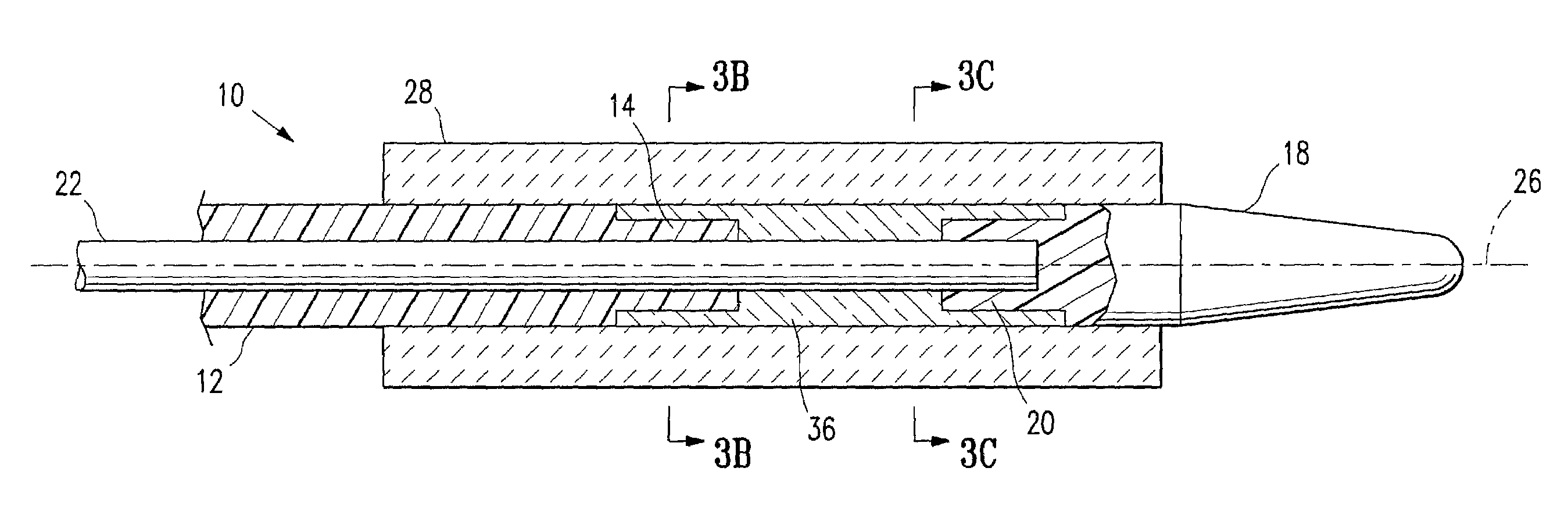
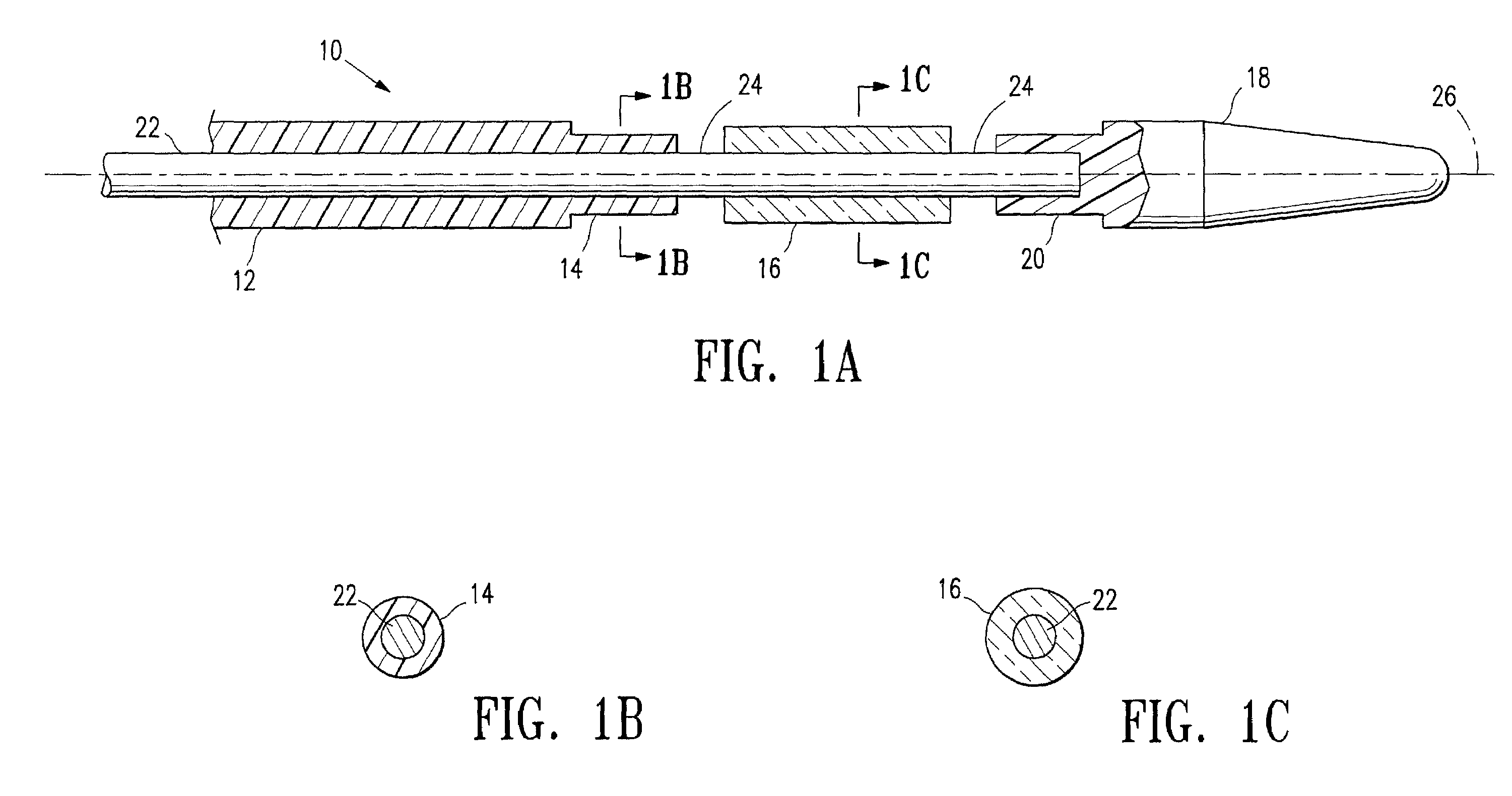
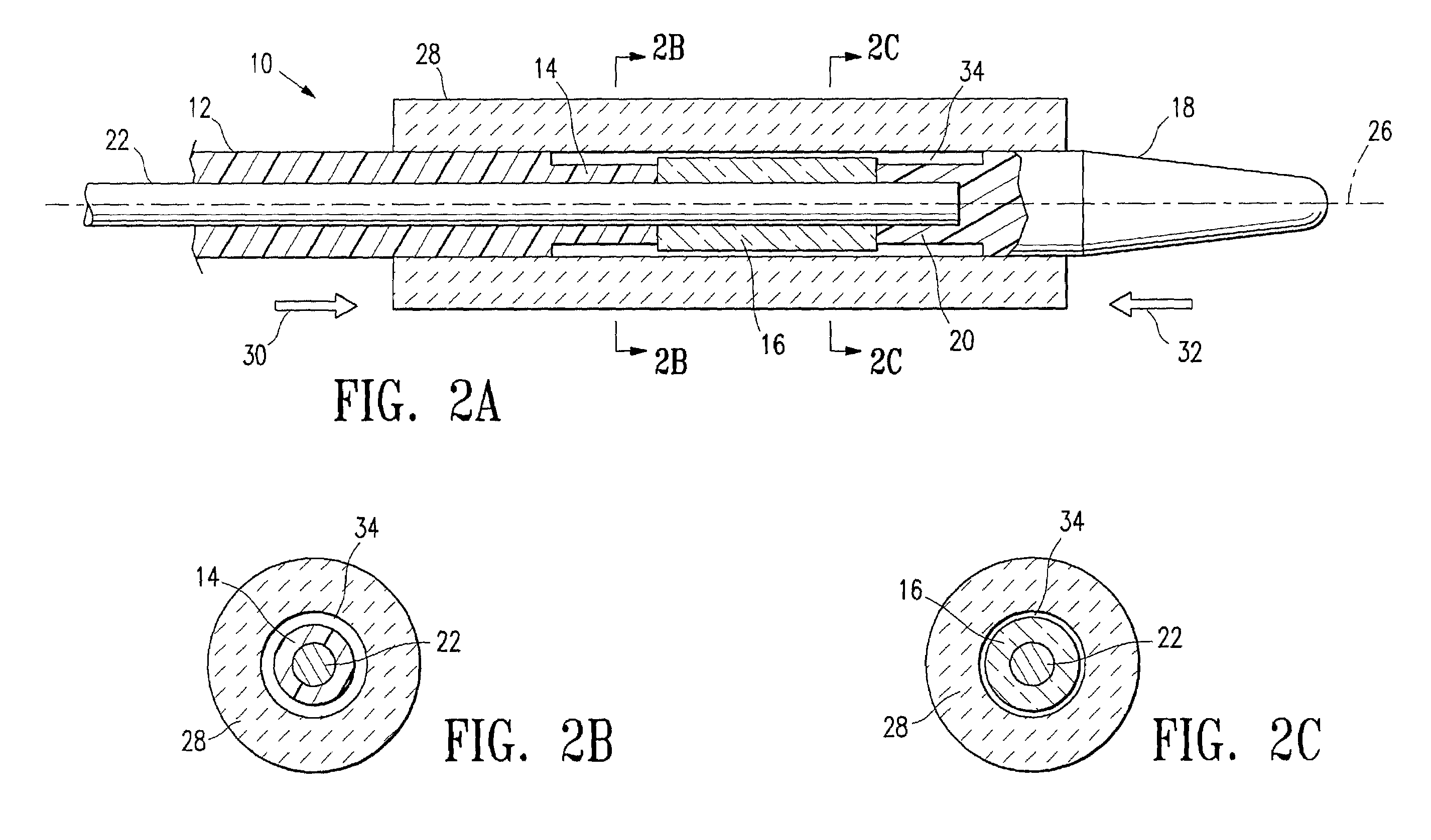
[0076]Window assemblies have been produced with the following items, where item numbers relate to similar components illustrated in the Figures. Item 22 is a mandrel and item 12, a hypotube, is a proximal tubular member. A hypotube is a tubular element useful in the manufacture of a guidewire, for example. Item 14 is a distal section of a proximal tubular member, that is, in this example, a distal portion of the hypotube. Item 16, a window preform, is an imaging window. Item 20, the proximal section of a distal member, is a proximal portion of a guidewire tip. Item 18, a distal member, is a guidewire tip. Item 28, a mold, is a mold formed from borosilicate glass tubing. Item 40, a fiberoptic assembly 40, as illustrated in FIG. 4 above, fits within bore 38 left by removal of mandrel 22. The following abbreviations are used below: “OD” for outer diameter; “ID” for inner diameter; “NiTi” for nickel titanium alloy, or nitinol; “PET” for polyethylene terephthalate; “SS” for stainless ste...

example 3

[0078]Windows comprising tensilized PET and polycarbonate were formed by the method of this example. Window preforms were cut to length (1–10 mm) from tubes of tensilized PET and of polycarbonate. A drill was used to create a concave taper on both ends of the window preform. This taper helps to center the proximal tubular member and the distal member. Where only one of the proximal tubular member and the distal member were to be attached, only one end of the window preform need be drilled to form a taper. A NiTi / Chromium Doped hypotube was used for the proximal tubular member. The proximal tubular member was next inserted into and clamped in a motorized collet. The proximal tubular member was then rotated in the collet and diameter of the end of the proximal tubular member was reduced using a grinding stone to form a distal section suitable for receiving the window preform. Next, a mandrel was inserted into the bore of the proximal tubular member, leaving sufficient length sticking ...


PUM

PropertyMeasurementUnit
lengthaaaaaaaaaa
lengthaaaaaaaaaa
temperatureaaaaaaaaaa

Abstract

Optical windows for intracorporeal devices, intracorporeal devices comprising a window and a method for forming a window for an intracorporeal device are provided. The method comprises placing within a mold an assembly comprising a mandrel located within a pair of parts separated by a collar of window material, heating the window preform effective to cause the window material to soften, and applying force to urge together the pair of parts to deform the window material so as to form a window. The intracorporeal devices, such as imaging devices, include guidewires, catheters, endoscopes. In addition, the method is suitable for joining plastic parts to other parts, such as metal and ceramic parts.

Description

FIELD OF THE INVENTION[0001]The present invention relates generally to methods and apparatus for manufacturing an optical window for an intracorporeal device that provides functional access to a body lumen, and to methods for joining parts together. In particular, the invention is directed to methods and apparatus for making an optical window for an imaging guidewire, catheter, or endoscope.BACKGROUND OF THE INVENTION[0002]Intracorporeal devices are devices suitable for introduction into a patient's body, for example, into a body lumen of a patient. Many clinical procedures require the insertion of wires, tubes, probes or other objects into a body lumen of a patient. For example, guidewires and catheters may be used for gaining access to the coronary vasculature, as in an angiogram or in angioplasty. A guidewire is a thin, flexible device used to provide a guiding rail to a desired location within the vasculature (or other body cavity) of a patient. A balloon catheter is a device wi...

Claims


Application Information

Patent Timeline
Patent Type & Authority Patents(United States)
IPC IPC(8): A61B5/00A61M25/00B29C35/08B29C35/12B29C43/18
CPCA61B5/0084A61M25/0009A61B5/0086
Inventor WEBLER, WILLIAM E.WHITT, MICHAEL D.JALISI, MARC M.CHUDY, ANDREJ M.PHILLIPS, KEVIN M.SPECK, MARC L.
Owner ABBOTT CARDIOVASCULAR
Why Eureka
Try Eureka