Multiple-axis control system for an optical switch

a control system and optical switch technology, applied in the direction of optics, optical elements, instruments, etc., can solve the problem of not providing the fastest possible switching speed, and achieve the effect of quick moving or tilting the mirror and quickly setting the switch to a new position

Active Publication Date: 2005-12-13
POLATIS PHOTONICS INC
View PDF16 Cites 42 Cited by
  • Summary
  • Abstract
  • Description
  • Claims
  • Application Information

AI Technical Summary

Benefits of technology

[0011]However, these prior art techniques have certain shortcomings. Consider first that MEMS and other actuators can apply a significant amount of mechanical force. These permit one to rapidly move or tilt a mirror and / or move the position of fiber tip end to steer the optical beam. For example, high natural frequencies of 1200 Hertz (Hz) or more can be accomplished with such actuators. This is at first instance quite an advantage, since providing a significant and strong motion force can assist with quickly setting the switch to a new position.

Problems solved by technology

While one could wait for such system responses to settle out (indeed some prior art systems do actually wait for such dynamics to settle) this approach does not provide for the fastest possible switching speed.

Method used


Image

  • Multiple-axis control system for an optical switch
  • Multiple-axis control system for an optical switch
  • Multiple-axis control system for an optical switch

Examples


Embodiment Construction

[0039]A description of preferred embodiments of the invention follows.

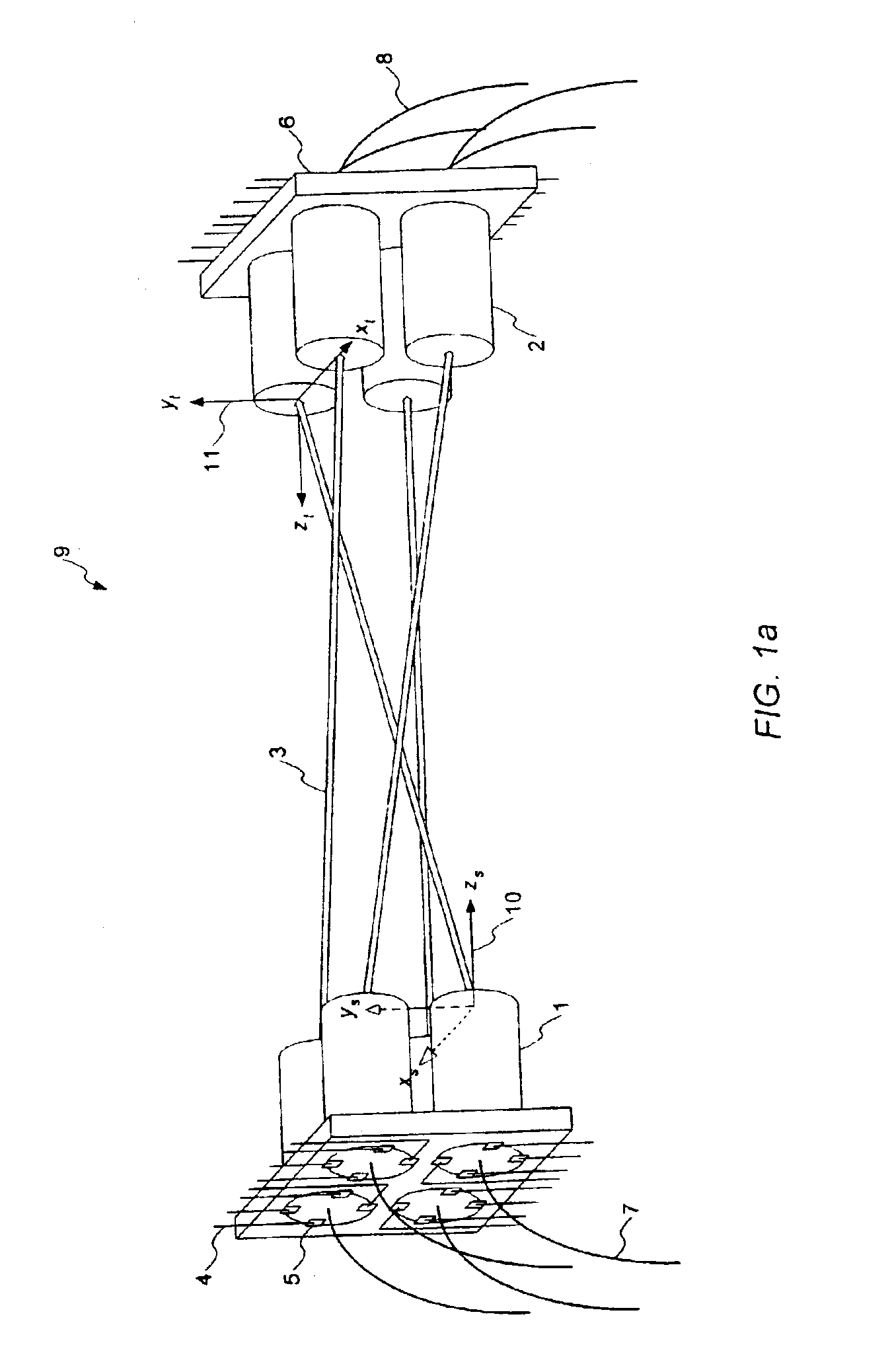
[0040]FIG. 1A details a typical all-optical free-space cross-connect switch consisting of an optical fabric 9 that includes optical source port emitters 1 and optical target port receivers 2. The emitters 1 can be selectively connected to the receivers 2 by varying the direction of the collimated beam 3 so as to impinge on the selected receiver 2. This can be accomplished by directly controlling the horizontal and / or vertical tilt angle of one of the emitters 1 or receivers 2. In other embodiments, mechanical actuators may control the horizontal or vertical direction of one or more micro-mirrors that control the resulting beam 3 or its detection. Any combination of active and / or passive emitters and / or receivers can be combined to form 1×N, N×1, N×N or M×N switch assemblies. It should also be understood that the assembly is bidirectional, i.e., input ports 1 could be considered to be output ports 2 and vice versa....


PUM


Abstract

A free space optical switch that uses both an open loop control mode and a closed loop control mode. The open loop control mode is used to transition to a state where at least some light is sensed at a destination port. A closed loop control mode is then used, whereby a series of controlled dither signals are adjusted for system dynamics. Modifying the dither signals in this matter allows moving actuators at a rate that is much closer to the natural frequency of the underlying system, and hence speeds up the system convergence process. Variable modulation amplitudes may be employed on the dither signals to maximize convergence speed. In particular, changes in the dither signal can be made in accordance with the change in amplitude as a function of a gradient along a parabola that models the optical system response. According to still further aspects, the dither signals may be compensated for a desired and selectable attenuation level of output optical power.

Description

CROSS REFERENCE TO RELATED APPLICATIONS[0001]This application claims the benefit of U.S. Provisional Application No. 60 / 365,457 entitled “Method and Apparatus for Switching or Attenuating Optical Signals,” filed Mar. 18, 2002. The entire teachings of this application, which is assigned to Continuum Photonics, Inc., is hereby incorporated herein by reference.BACKGROUND OF THE INVENTION[0002]This invention relates to a beam steering optical switch and in particular to a control system for a free-space optical cross-connect switch with actuation, such as piezoelectric actuation, or any other micro-optical positioning or beam-steering device.[0003]Communication signals are now commonly transmitted across networks using compact optical fiber bundles that support substantial transmission capacity. Given the ever-increasing demands for improved signal quality and bandwidth, it is anticipated that fiber optic communications will continue to supplant copper wire based technologies for many y...

Claims


Application Information

Patent Timeline
Patent Type & Authority Patents(United States)
IPC IPC(8): G02B6/35H04Q11/00
CPCG02B6/3502G02B6/359H04Q11/0005G02B6/3556G02B6/3558G02B6/3578H04Q2011/003H04Q2011/0039H04Q2011/0049
Inventor GHANDI, KAMYARHAGOOD, IV, NESBITT WARDGLENN, TIMOTHY SCOTT
Owner POLATIS PHOTONICS INC
Why Eureka
Try Eureka