Medical imaging, diagnosis, and therapy using a scanning single optical fiber system

a single optical fiber and imaging technology, applied in the field of optical fiber systems, can solve the problems of inability to easily integrate the current tools used for mimps, the size of the resultant instrument is too large, and the flexible scope cannot be made smaller than this limit, and achieves good fov and high resolution

Inactive Publication Date: 2005-12-13
UNIV OF WASHINGTON
View PDF23 Cites 560 Cited by
  • Summary
  • Abstract
  • Description
  • Claims
  • Application Information

AI Technical Summary

Benefits of technology

[0014]In most embodiments of the present invention, at least one lens is disposed between the distal end of the light guide and the ROI, for focusing the imaging light and the light produced by the therapy light source onto the ROI. Preferably, to provide high resolution and a good FOV, a lens is mounted on the distal end of the light guide in one embodiment. In this configuration, as the scanning actuator drives the distal end of the light guide in a resonance mode to scan the ROI, the lens that is mounted on the distal end of the light guide has sufficient mass so that the lens generally rotates about a center of the lens as the light guide moves. The movement of the light guide changes the direction in which light is emitted from the lens, to scan the ROI.

Problems solved by technology

The current tools used for MIMPs cannot readily be integrated without increasing the size of the resultant instrument to an excessive degree.
Currently, flexible scopes cannot be made smaller than this limit unless image field of view (FOV) or resolution is sacrificed.
Although imaging and some diagnostic capability can be integrated into existing scopes, such as standard tissue imaging in combination with fluorescence for early detection of cancers, the optical systems of current flexible scopes cannot provide integrated diagnoses and therapies at the required degrees of performance, size, and price that will be demanded in the future by medical practitioners.
Thus, the diameter of these flexible scopes employed for remote imaging cannot be reduced to smaller than the image size.
All commercially available scopes suffer from this fundamental tradeoff between high image quality and small size.
Since, for the reasons noted above, the current design for flexible scopes cannot readily be reduced in size without reducing imaging performance, the options for integrating diagnostic and therapeutic applications with an imaging system would appear to require an increase in the size of the instrument or use of separate instruments for each function.
However, the white light illumination for standard endoscopic imaging is typically provided through an optical fiber bundle that diffusely illuminates the tissue and is incapable of providing a directed optical energy at high intensity and resolution to produce effective optical therapies, and will often not have the characteristics required for diagnostic processes.
Therefore, any optical therapies that require directed illumination of high intensity light, such as PDT and laser surgery, or any diagnostic processes that also require a special light source cannot use existing optical designs for flexible imaging scopes, but instead, must rely on a second optical pathway and separate control mechanisms.
Furthermore, the therapeutic instrument often blocks the practitioner's direct view of the ROI with the imaging tool, making highly accurate therapies quite difficult for the medical practitioner to achieve.
Currently, none of the instruments available provide these capabilities and cannot be easily modified to provide such capabilities.

Method used


Image

  • Medical imaging, diagnosis, and therapy using a scanning single optical fiber system
  • Medical imaging, diagnosis, and therapy using a scanning single optical fiber system
  • Medical imaging, diagnosis, and therapy using a scanning single optical fiber system

Examples


Embodiment Construction

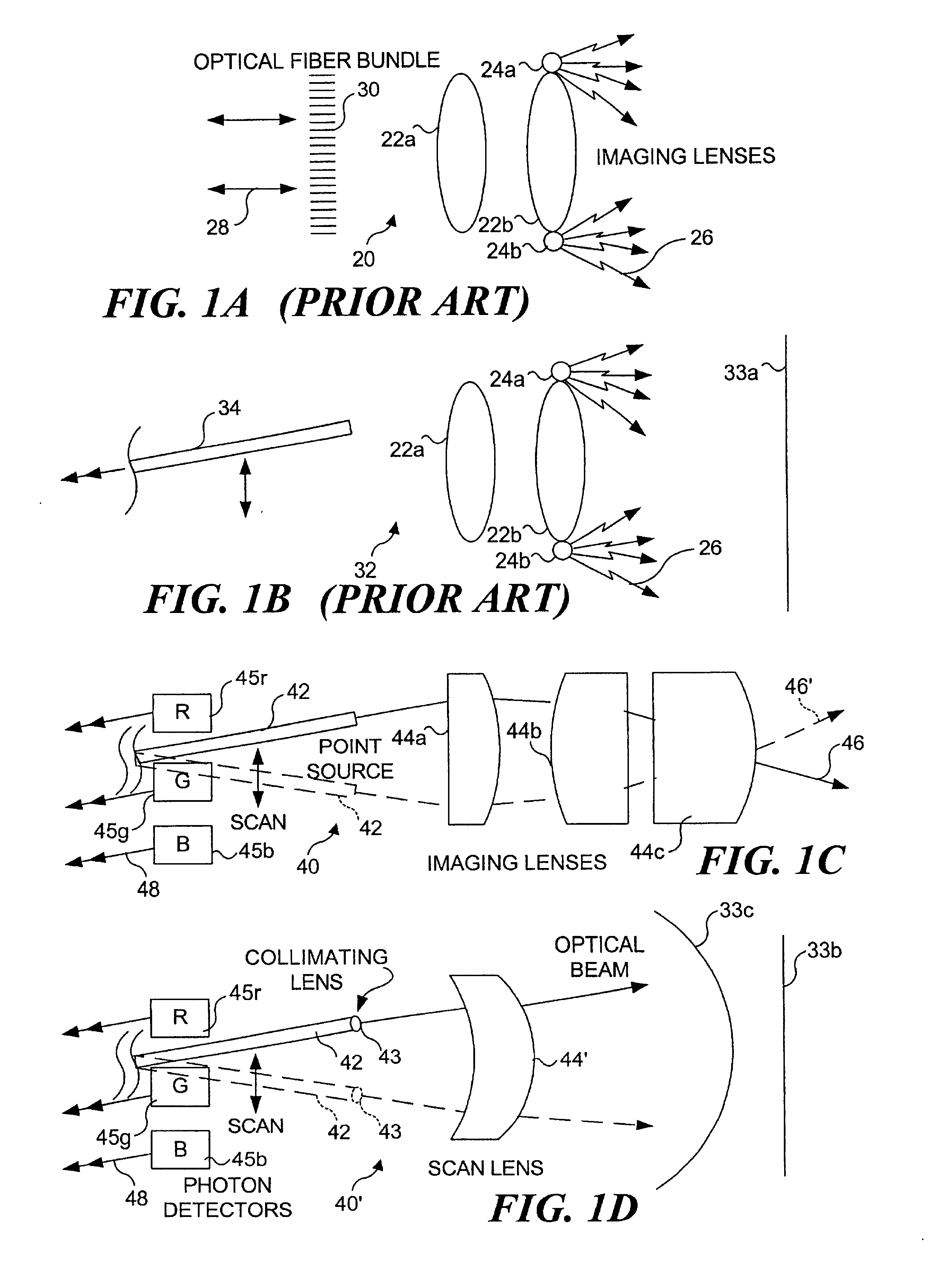
Prior Art Imaging Endoscopes

[0050]With reference to FIG. 1A, the distal end of a flexible endoscope 20 is illustrated schematically, indicating how a non-scanning imaging process is implemented. Imaging lenses 22a and 22b receive light reflected from an ROI within a patient's body illuminated with light sources 24a and 24b. Although shown adjacent imaging lens 22b, these light sources may alternatively be disposed external to the patient's body so that light produced by the sources is conveyed through optical fibers (not shown) to the internal site. Light that has passed through imaging lenses 22a and 22b is received by a pixel array optical fiber bundle 30 (or alternatively by a pixel array camera—not shown). In this case, each camera or detector disposed at the distal end within a patient's body, or proximally at the end of the fiber optic bundle through which the light from imaging lenses 22a and 22b is conveyed outside the patient's body, corresponds to only a single image pixel...


PUM

PropertyMeasurementUnit
sizeaaaaaaaaaa
core diameteraaaaaaaaaa
diameteraaaaaaaaaa

Abstract

An integrated endoscopic image acquisition and therapeutic delivery system for use in minimally invasive medical procedures (MIMPs). The system uses directed and scanned optical illumination provided by a scanning optical fiber or light waveguide that is driven by a piezoelectric or other electromechanical actuator included at a distal end of an integrated imaging and diagnostic/therapeutic instrument. The directed illumination provides high resolution imaging, at a wide field of view (FOV), and in full color that matches or excels the images produced by conventional flexible endoscopes. When using scanned optical illumination, the size and number of the photon detectors do not limit the resolution and number of pixels of the resulting image. Additional features include enhancement of topographical features, stereoscopic viewing, and accurate measurement of feature sizes of a region of interest in a patient's body that facilitate providing diagnosis, monitoring, and/or therapy with the instrument.

Description

RELATED APPLICATIONS[0001]This application is based on prior copending provisional patent application Ser. No. 60 / 212,411, filed on Jun. 19, 2000, the benefit of the filing date of which is hereby claimed under 35 U.S.C. § 119(e).FIELD OF THE INVENTION[0002]The present invention generally relates to an optical fiber system that conveys light to and from a region of interest (ROI) on or within a living body, and more specifically, to a system that is selectively used for both imaging the ROI to facilitate a diagnosis, and for delivering therapy to the ROI.BACKGROUND OF THE INVENTION[0003]The burgeoning field of minimally invasive medical procedures (MIMPs) has increased the demand for systems that produce less tissue damage and trauma, faster recovery times, and lower risks to the patient. Ideally, the practitioner of MIMPs requires smaller instruments that perform a greater variety of functions. Furthermore, a “one-instrument-does-all” approach must add simplicity, not complexity, b...

Claims


Application Information

Patent Timeline
Patent Type & Authority Patents(United States)
IPC IPC(8): G01N21/64A61B1/00A61B1/005A61B1/04A61B5/00A61B5/107A61B18/20A61N5/06G01N21/27G01Q20/02G02B6/26G02B6/32G02B6/35G02B26/10H04N7/18
CPCA61B1/00048A61B1/0008A61B1/00165A61B1/00167A61B1/00172A61B1/00183A61B1/0051A61B1/0638A61B5/0062G02B6/241G02B6/262G02B26/10A61B1/07A61B1/00193A61B1/043A61B5/0066A61B5/0068A61B5/0071A61B5/0075A61B5/0084A61B5/1076A61N5/0601A61N5/062A61N2005/063G02B6/32G02B6/3502G02B6/3566G02B6/357G02B6/3572G02B6/3578A61B1/009A61B1/0655
Inventor SEIBEL, ERIC J.
Owner UNIV OF WASHINGTON
Why Eureka
Try Eureka