
Wireless terminal device

Inactive Publication Date: 2005-12-27
MITSUBISHI ELECTRIC CORP
View PDF13 Cites 7 Cited by
  • Summary
  • Abstract
  • Description
  • Claims
  • Application Information

AI Technical Summary

Benefits of technology

[0018]The present invention is a wireless terminal device wherein a received signal is supplied to a variable gain circuit having a variable gain, a level of the received signal supplied to the variable gain circuit is detected by a first level detection circuit and, an input voltage range of the first level detection circuit is selected wide. An output signal of the variable gain circuit is converted into a digital signal by a conversion circuit, a level of an input signal or an output signal of the conversion cir

Problems solved by technology

In the heterodyne conversion system, however, as the intermediate frequency exists an intermediate frequency circuit, such as a band-pass filter, must be provided, resulting in the increase in the number of components and space for mounting the components.
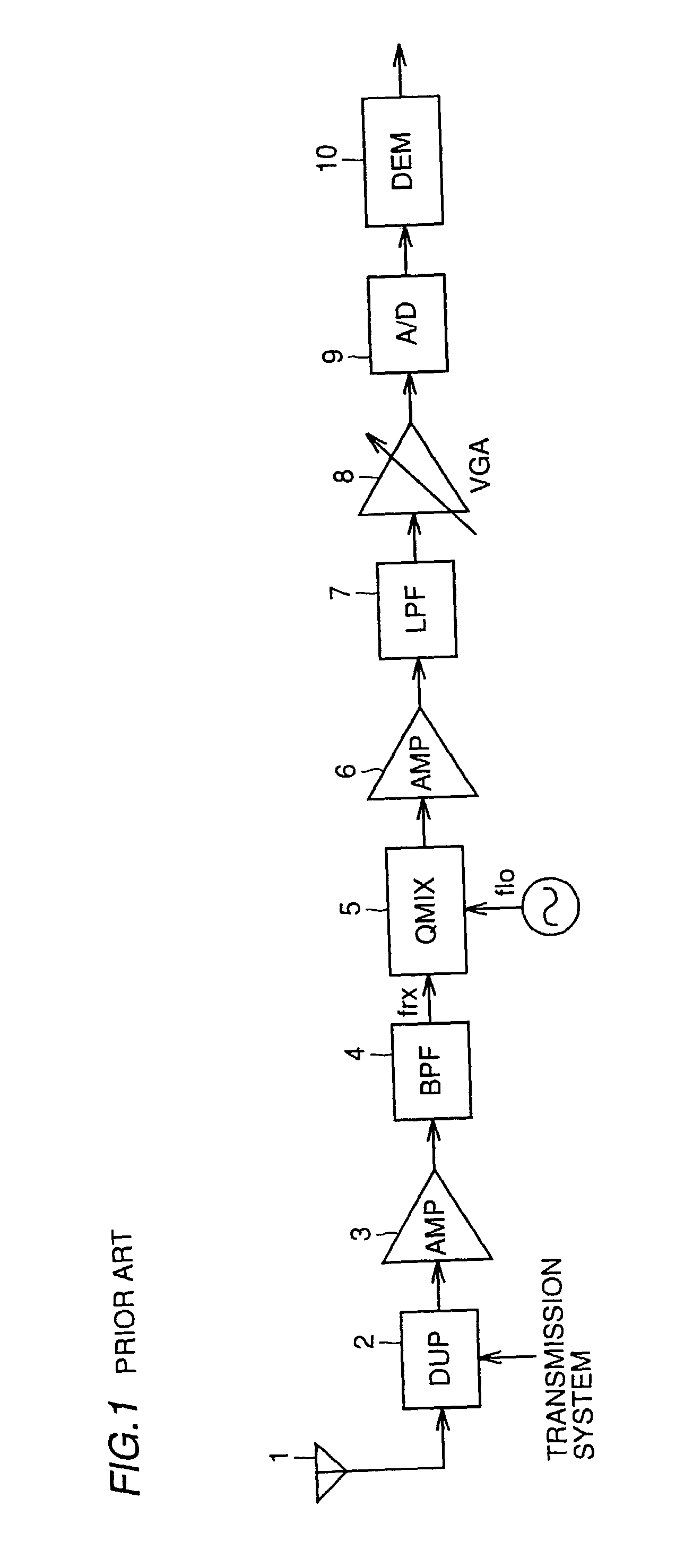
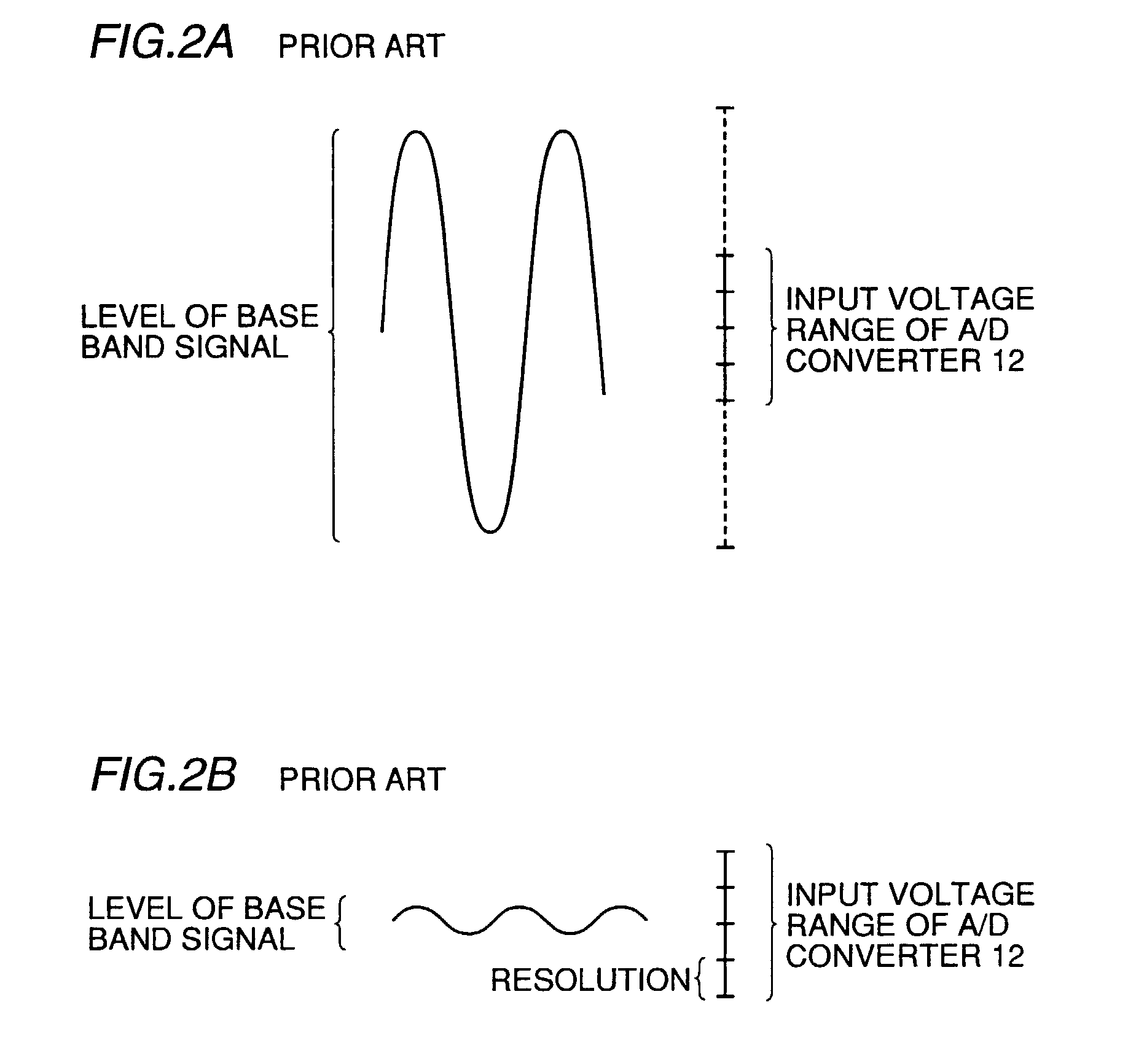
In the portable telephone, however, the level of the base band signal supplied to A / D converter 9 at the onset of the operation, such as at power-on, is not predictable.
Such A / D converters, however, consume large current and are large in circuit size and their use in portable telephones is subjected to a certain limitation.

Method used


Image

  • Wireless terminal device
  • Wireless terminal device
  • Wireless terminal device

Examples


first embodiment

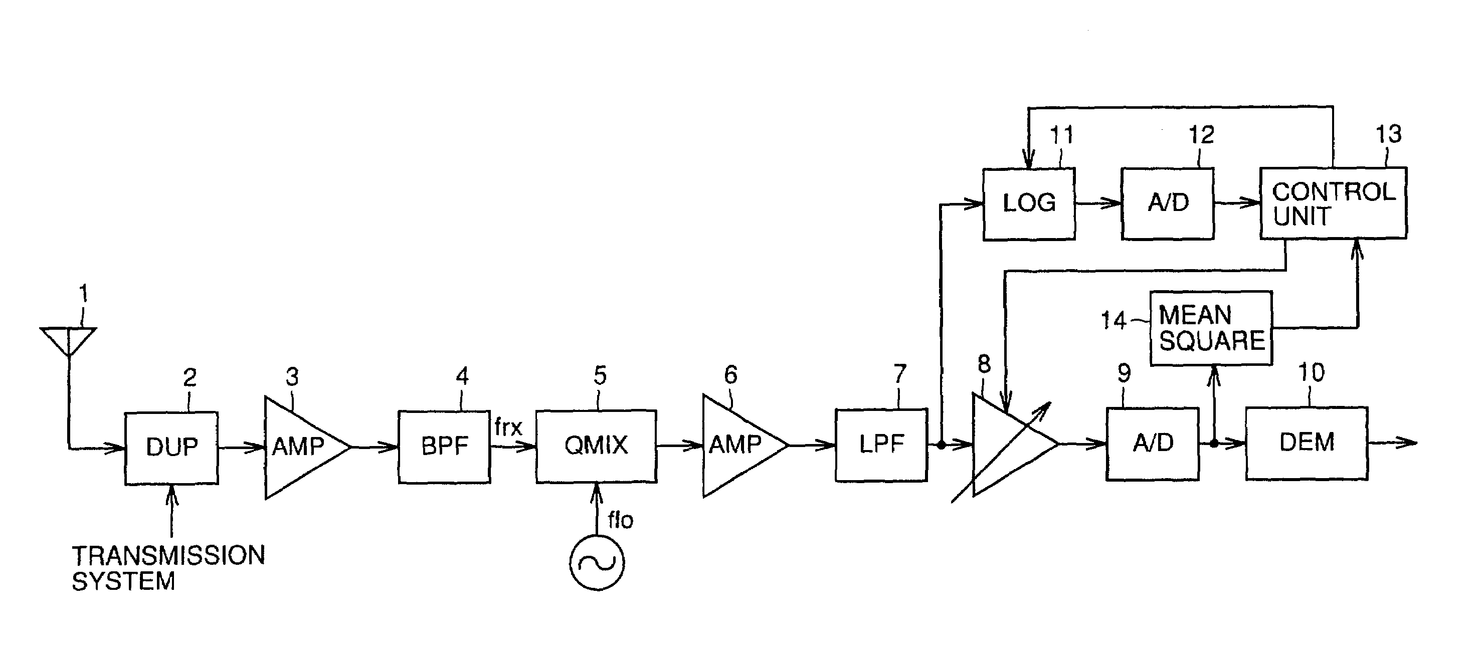
[0040]FIG. 3 is a block diagram of the present invention. In FIG. 3, the structure from an antenna 1 up to a demodulator 10 is same with that of FIG. 1. In this embodiment, a logarithmic amplifier 11, an A / D converter 12 and a control unit 13 are added. Logarithmic amplifier 11 detects a level of a base band signal supplied to variable gain amplifier 8. Here, logarithmic amplifier 11 does not detect the level of the input signal with a high accuracy but has a wide input voltage range even though with somewhat coarse accuracy. Here, the wide input voltage range is required to allow detection of input signals from a low level to a high level.

[0041]Here, the necessary detection range is a range in which a minimum bit number of A / D converter 9 required for the demodulation can be derived. (The required minimum bit number of A / D converter 9 is derived through test, simulation or the like and the kind of means utilized is not of importance here. The numerical value thereof is also differe...

third embodiment

[0050]FIG. 7 is a block diagram of the present invention. In the embodiment shown in FIG. 7, the power is supplied to logarithmic amplifier 11 only at the start of the operation and when the feedforward control is finished the power supply to logarithmic amplifier 11 is cut off or reduced to decrease the current consumption. For this end, a control signal is supplied from control unit 13 to logarithmic amplifier 11.

[0051]FIG. 8 is a flow chart referenced for describing a specific operation of the embodiment shown in FIG. 7. Next, a specific operation of the embodiment shown in FIG. 7 will be described with reference to FIG. 8. When the operation starts, control unit 13 supplies power to logarithmic amplifier 11 at step S11 and then, the same operations as in steps S1 to S3 of FIG. 4 are performed in steps S12, S13 and S14 to control the gain of variable gain amplifier 9. Then at step S15, the power supply to logarithmic amplifier 11 is cut off or reduced.

[0052]Hence, in this embodim...

fourth embodiment

[0054]FIGS. 9A and 9B are diagrams referenced for describing the fourth embodiment which is a method for detecting, when a caller moves from one wireless area of one base station to a wireless area of an adjacent base station which movement is generally referred to as a hand-over, using a communication system such as CDMA, an electric wave for a securable line to the adjacent base station while securing a line to the base station and FIG. 10 is a flow chart referenced for describing the operation thereof.

[0055]When the portable telephone is used, the data amount transmitted between a base station and a caller is constant in a normal operation as shown in FIG. 9A. The caller, however,.sometimes moves from one wireless area of one base station to another wireless area of an adjacent base station. In this case, the level of the signal in the adjacent base station is not known. Hence, a level of a line is detected at certain intervals to allow securing of the adjacent base station other...


PUM


Abstract

A level of a base band signal at an input side of a variable gain amplification circuit is detected by a logarithmic amplifier having a wide input voltage range at a start of an operation, a control unit then performs a coarse feedforward control on a gain of the variable gain amplifier based on the detected level and finds a level of an output of an A / D converter by a mean square deriving circuit and inputs the resulting signal to the control unit. Then the control unit performs a fine feedback control on the variable gain amplifier based on the detected level.

Description

REFERENCE TO RELATED APPLICATION[0001]This Application is a continuation of application Ser. No. 09 / 694,678, filed Oct. 24, 2000 (now U.S. Pat. No. 6,683,925), which is a continuation of National Stage of International Application No. PCT / JP99 / 00851, filed Feb. 24, 1999, the disclosure of which is incorporated by reference herein.BACKGROUND OF THE INVENTION[0002]1. Field of the Invention[0003]The present invention relates to wireless terminal devices and, more particularly to a wireless terminal device, such as a portable telephone, having a receiving unit with a direct conversion system in which a received signal is converted directly into a base band signal.[0004]2. Description of the Background Art[0005]In a heterodyne conversion system for receivers, which has been well known, a received signal is converted into an intermediate frequency (IF) signal by a mixer (MIX) and then an unwanted wave is removed by a band-pass filter (BPF) for the IF. After that, complex envelope detectio...

Claims


Application Information

Patent Timeline
IPC IPC(8): H03G3/00H04L27/08
CPCH03G3/001
Inventor KATSURA, TAKATOSHIITOH, KENJIFUKUYAMA, SHINJIROUMOCHIZUKI, MITSURUNAGANO, HIROAKIMATSUNAMI, YOSHINORIISHIZU, FUMIOHAYASHI, RYOJI
Owner MITSUBISHI ELECTRIC CORP
Learn More