

Apparatus and methods for tendon or ligament repair
- Summary
- Abstract
- Description
- Claims
- Application Information
AI Technical Summary
Benefits of technology
Problems solved by technology
Method used
Image

Examples
first embodiment
[0179]A first way of securing the suture is with a variety of buttons. A first embodiment is shown in FIG. 15 which shows the use of a sliding anchor button or body 126. A surgeon makes a stab or slit wound 128 in the tendon 106 in an area generally under the second incision 108 made on the first side 110 of the first incision 100. The sliding anchor button or body 126 slips onto the suture 118 and into the stab wound 128 under the exterior surface 129 of tendon 106. The sliding anchor button 126 has burrs 130 which serve to assist in holding sliding anchor button 126 in place in tendon 106 once it reaches the desired location. The burrs 130 are directed such that they are facing towards the tear 104 and generally outwardly from the suture 118 and serve to reduce the possible motion of sliding anchor button 126 and to distribute the axial load. In order to properly place the sliding anchor button 126, a tool 132 should be used which is capable of keeping the exterior surface of slid...
second embodiment
[0180]securing buttons is shown in FIG. 17. In FIG. 17, two sutures 118 are used to hold first side 122 and second side 124 in abutting relationship, as was mentioned above. In such a case, a first suture 118 must be placed to one side of the center 120 of tendon 106 and a second suture 118 must be placed to another side of the center 120 of tendon 106. If this embodiment is used, no stab wound need be made in the tendon 106. In this embodiment, once the suture is placed, the tab buttons 136 slide onto suture 118 until they reach the exterior surface 129. The suture 118 may be placed under greater tension by pushing tab buttons 136 such that they place some pressure on the exterior surface 129 of tendon 106. Once the tab buttons 136 have been appropriately placed, they are swaged or crimped to suture 118 such that they are attached to and circumscribe at least a part of suture 118, as shown most clearly in FIG. 17A, by a swaging tool 140. Preferably, as shown in FIG. 17B, the tab bu...
third embodiment
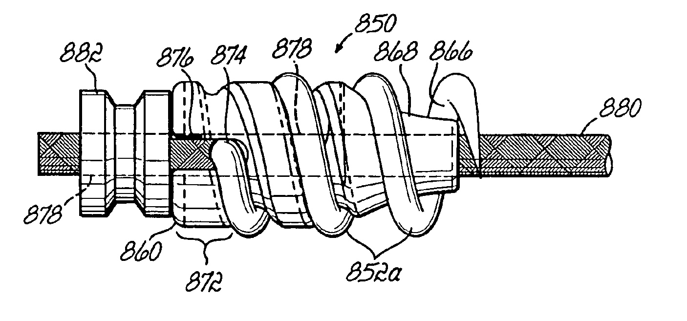
[0182]Turning now to FIG. 19, buttons is shown. The transverse button 162 is again used in conjunction with two sutures 118, inserted as described above. The transverse button 162, as shown in FIG. 19A, is attached to an partially circumscribes a first suture 118 and is swaged or crimped onto the first suture 118 with a swaging tool, such as tool 140. Another transverse button 162 is attached to and partially circumscribes a second suture 118 and is swaged or crimped onto the second suture 118 with a swaging tool, such as tool 140. In this embodiment, the transverse buttons 162 are attached to each other by a telescoping mating pin 164. Attached to one of the transverse buttons 162 is the male portion 166 of the pin 164, and attached to the other transverse button 162 is the female portion 168 of the pin 164. The male portion 166 and the female portion 168 are pushed towards each other through tendon 106. When male portion 166 and female portion 168 reach each other, they ratchet an...
PUM
 Abstract
Description
Claims
Application Information