Liquid cooling system and personal computer using thereof

Inactive Publication Date: 2006-01-17
HITACHI LTD
View PDF16 Cites 32 Cited by
  • Summary
  • Abstract
  • Description
  • Claims
  • Application Information

AI Technical Summary

Benefits of technology

[0027]In the liquid cooling system according to the present invention, since the cooling liquid is circulated within the flow passage with the pulsation thereof, by use of such a reciprocating pump therein, the volume change ΔVp in the pump housing due to supply of the pulsation (i.e., due to the reciprocating movement) can be obtained from Q/(number of vibrations f); therefore, the relationship between the volume change ΔVp and the pressure P can be drawn as shown in FIG. 15. Also, since the pressure P applied on the pipe and the volume change ΔVs in the pipe proportional to each other, the relationship comes to be indicated by a straight line (1), for example. In this instance, at a point where the straight line (1) and the characteristic curve of the pump cross, pressure P1 and volume change ΔV1 can be determined. In a case of forming an open loop, the volume change is determined by the pressure loss P0 of the pipe, thereby obtaining the volume change ΔV0, however if a rigid or hard pipe having small volume change therein is used, as indicated by (1), only the volume change of ΔV1 can be obtained, which is smaller than ΔV0. Accordingly, the flow rate is reduced, and, therefore, the cooling performance also is reduced. On the contrary, in a case where the volume change with respect to the pressure is large, as is indicated by (1), namely, in the case of using a soft pipe, since the volume change ΔV0 becomes large at the crossing point of the straight line (2) with the characteristic curve of the pump, the primary volume change can be obta

Problems solved by technology

A pump is necessary for circulation of liquid in a liquid cooling system; however, with a pump of rotational type, which is typically used, it

Method used


Image

  • Liquid cooling system and personal computer using thereof
  • Liquid cooling system and personal computer using thereof
  • Liquid cooling system and personal computer using thereof

Examples


first embodiment

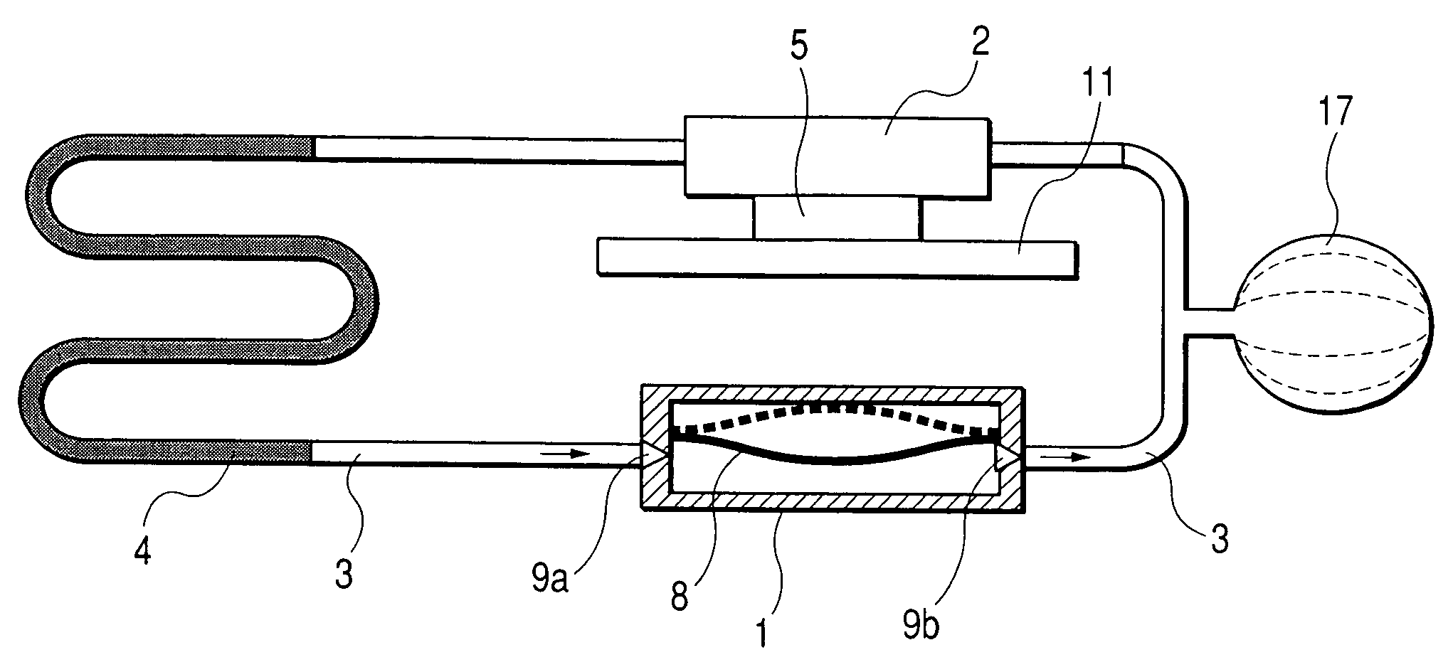
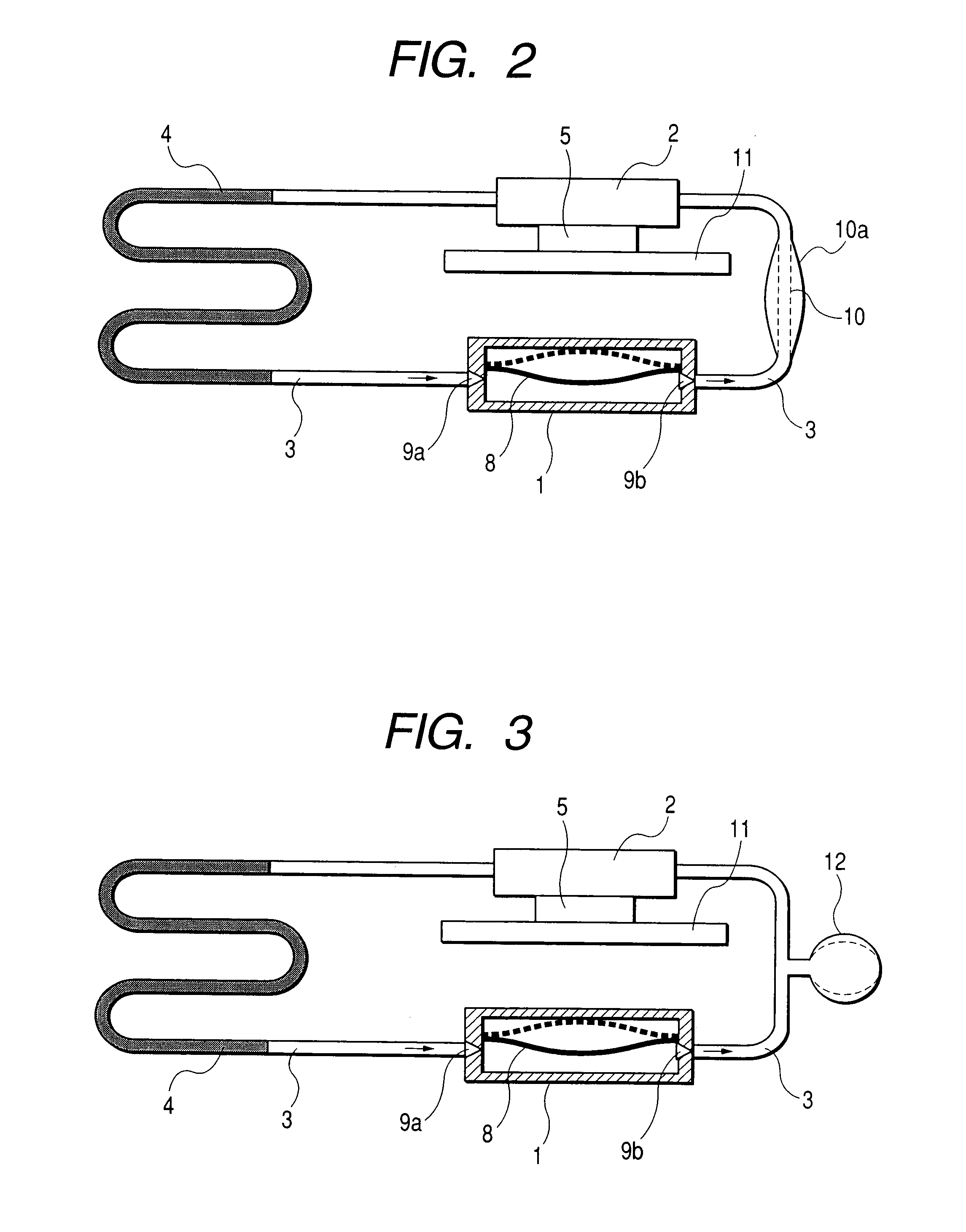
[0047]FIG. 2 diagrammatically shows the cooling system of the notebook-type personal computer shown in FIG. 1. The pump 1, the heat receiving jacket, which is in thermal contact with the semiconductor element 5 mounted on a print circuit board 11, and the heat radiation pipe 4 are connected by means of the connector pipes 3. The pump 1 is constructed with a housing having a diaphragm 8 that is mounted for reciprocal movement therein and check valves 9a and 9b. A portion of one of the connector pipes 3 is made of a soft material, so as to form an expansible portion 10. When the diaphragm 8 moves to the solid line position shown in the figure, the cooling liquid is suppressed, and the check valve 9b is opened. Then, due to the pressure of the cooling liquid, the expansible portion 10 is expanded to the shape 10a, therefore the cooling liquid moves out of the pumps in the direction of the arrow. Next, when the diaphragm comes back to the position shown by the broken line, since the pre...

fifth embodiment

[0063]However, if rubber or resin is used, the molecules of the cooling liquid tend to diffuse therein, as was explained in connection with the fifth embodiment, therefore, the cooling liquid may diffuse away into the atmosphere. According to the present embodiment, since the surface of the connector pipe 3 is covered with the metal film 18, it is possible to prevent loss of the cooling liquid from the system. Also, as shown in FIG. 11, the same effect can be obtained by covering the connector pipe with a resin sheet 19, including a metal film 19a and a resin film 19b. In this case, it does not matter if there a space is formed between the resin sheet 19 and the connector pipe 3, however, they must closely adhere to each other at both ends thereof.

seventh embodiment

[0064]FIG. 12 diagrammatically shows the liquid cooling system according to the present invention. In the present embodiment, two pumps are provided in series, thereby forming a flow passage as a closed loop. Solid lines and broken lines of the diaphragms 8 and 8′ correspond to each other. When the diaphragm 9 of the pump 1 is at the position shown by the solid line, so as to pressurize the cooling liquid, the diaphragm 8′ of the pump 1′ is at the position shown in the solid line, therefore the cooling liquid emitted from the pump 1 flows into the pump 1′. In this manner, since the two pumps are shifted in operation by 180 degree as to the phase of reciprocal movements of the diaphragms thereof, the cooling liquid can flow in the direction of arrows, therefore obtaining effects that are totally the same as those of the other embodiments, i.e., it is possible to draw out the characteristics or performance of the liquid cooling system with high efficiency, thereby to provide a system ...


PUM


Abstract

A liquid cooling system having a circulator for circulating a cooling liquid therethrough including an input portion for receiving the cooling liquid and a separate output portion for supplying the cooling liquid. A heat receiving jacket supplied with the cooling liquid from the circulator and positioned to received heat generated from a heat generation body, a heat radiation portion for radiating heat which is supplied by the cooling liquid passing through the heat receiving jacket, and a member for circulating the cooling liquid passing through the heat radiation portion into the circulation means so that the cooling liquid circulates within a closed flow passage. An accumulating portion is further formed within a portion of the closed flow passage for accumulating the cooling liquid therein.

Description

CROSS REFERENCE TO RELATED APPLICATION[0001]This is a continuation of U.S. application Ser. No. 09 / 921,925, filed Aug. 6, 2001, now U.S. Pat. No. 6,741,464, the subject matter of which is incorporated by reference herein.BACKGROUND OF THE INVENTION[0002]The present invention relates to a liquid cooling system for cooling a body that is generating heat, and, in particular, to a liquid cooling system that is suitable for use in a small and / or thin electronic device.[0003]Semiconductor devices that are used in electronic devices, such as a computer, etc., generate heat during their operation. In particular, high-integrated semiconductor devices, in recent years, have produced an increased amount of heat generation. Since the semiconductor device will be damaged if the temperature thereof exceeds a certain value, cooling is necessary to prevent damage to the semiconductor device having a large amount of heat generation during use.[0004]For cooling the semiconductor device of an electron...

Claims


Application Information

Patent Timeline
IPC IPC(8): G06F1/20F25D17/02F25D9/00H05K7/20
CPCG06F1/203G06F2200/203G06F2200/201
Inventor KITANO, MAKOTONAGANAWA, TAKASHIYOSHITOMI, YUJIMINAMITANI, RINTAROOHASHI, SHIGEOASHIWAKE, NORIYUKIKONDO, YOSHIHIRONAKAGAWA, TSUYOSHI
Owner HITACHI LTD
Why Eureka
Try Eureka