Miniature x-ray tube with micro cathode

Active Publication Date: 2006-01-17
XOFT INC
View PDF5 Cites 66 Cited by
  • Summary
  • Abstract
  • Description
  • Claims
  • Application Information

AI Technical Summary

Benefits of technology

[0009]By these MEMS techniques, extremely fine micro cathodes can be produced, having emissive output and filament lifetimes consistent with conventional electron tube technology. The low heater operating current of such a fine filament reduces the conductor size requirement in the glass fiber, and in a disclosed preferred embodiment this conductor size can be less than about 0.003 inch in diameter.
[0010]To operate the x-ray tube with the micro cathode, two cathode heating current leads need to be provided to supply the filament of the micro cathode, and for a grounded anode configuration these leads need to electrically float at the tube high voltage, requiring that both the leads be insulated from the tube ground return. These first and second electrical conductors in the heating circuit can be configured coaxially, with a center conductor and a coaxial conductor surrounded by additional glass to provide the insulation. Alternatively, a twin axial configuration can be used, providing two buried leads but with higher field gradients. A central channel with two D-shaped conductors back to back provides maximum dielectric strength with reasonable field gradients from the conductors. Other configuration are also possible, including an insulated center conductor and coating on the inside surface of the fiber for the second conductor.
[0011]An important feature in one principal embodiment of the invention is the glass fiber connecting the controller to the x-ray tube. This glass fiber provides a continuous glass path from the controller to the cathode within the x-ray tube, and involves a hermetic vacuum seal between the distal end of the glass fiber and the cathode assembly, the hermetic vacuum seal being vital in achieving short length x-ray tubes that are deliverable within the coronary arteries or other cavities or passages. In addition to providing the hermetic vacuum seal capability, the glass fiber provides needed dielectric strength as noted above for holding off the high voltage within the conductors to ground. If the fiber is made with enough glass thickness to hold off the full x-ray tube operating voltage, the fiber tends to become so thick as not

Problems solved by technology

Such an extended rigid region would make deliverabil

Method used


Image

  • Miniature x-ray tube with micro cathode
  • Miniature x-ray tube with micro cathode
  • Miniature x-ray tube with micro cathode

Examples


Embodiment Construction

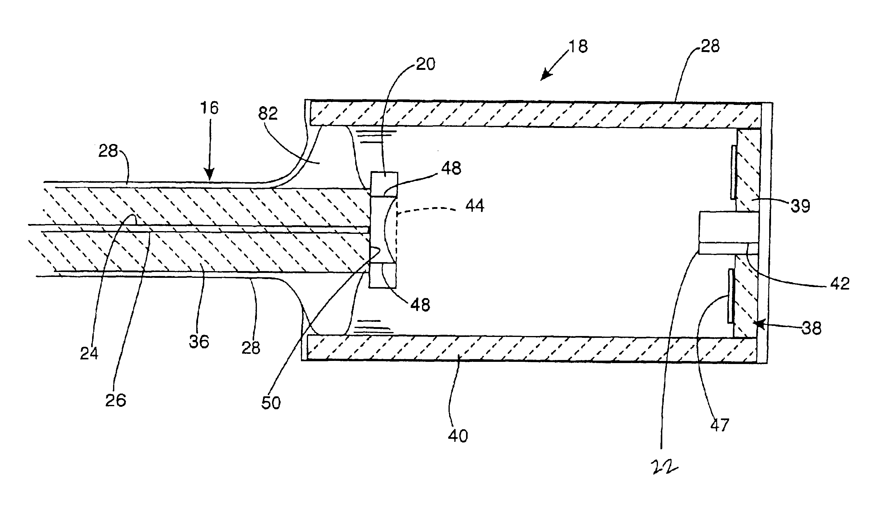
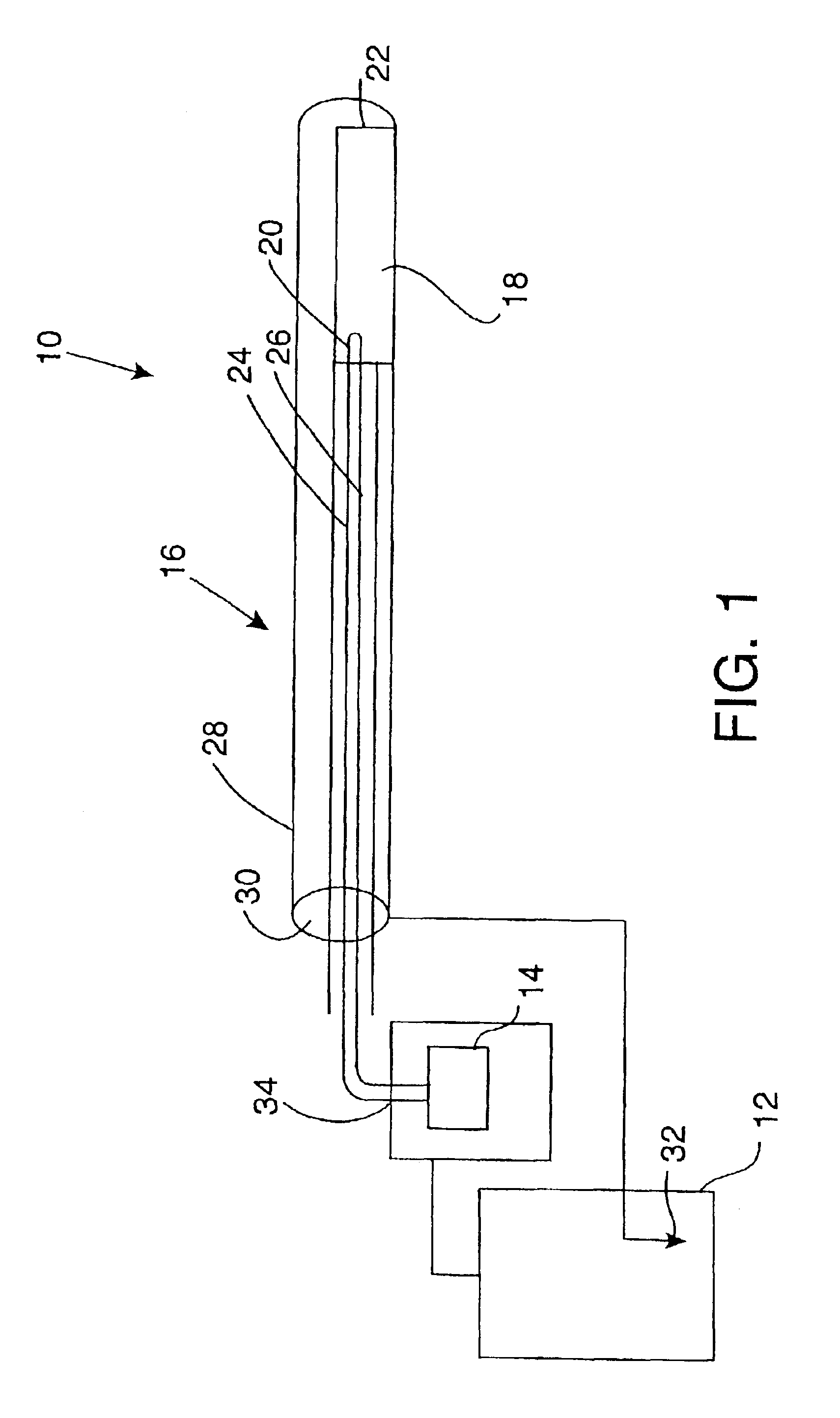
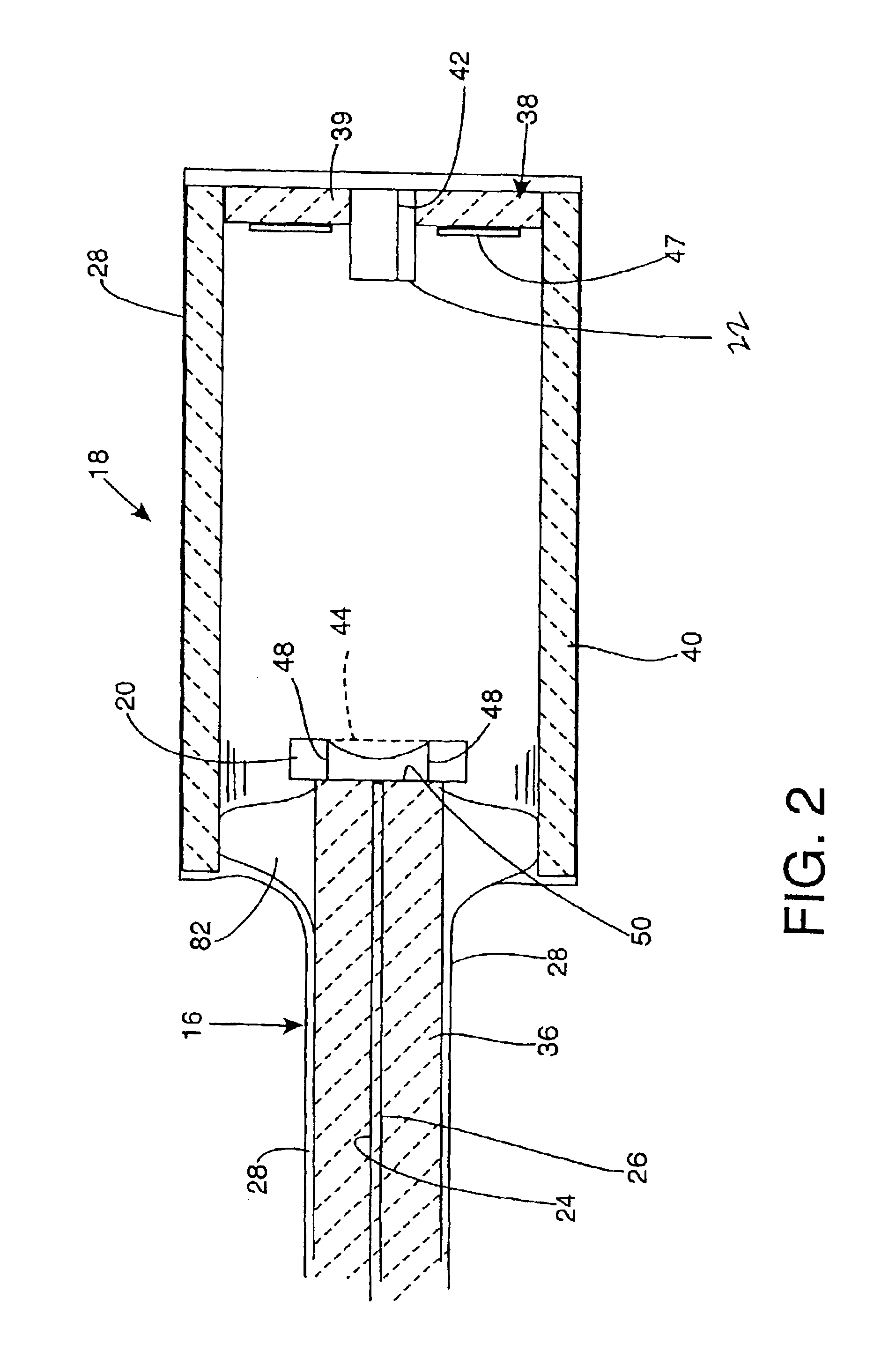
[0026]In the drawings, FIG. 1 shows schematically and not to scale the major elements of an x-ray device 10 for intra-vascular and other use in body cavities, comprising a controller 12 with high voltage power supply, a battery or other low voltage power supply 14, which can be included within the controller 12, a flexible probe line 16 extending from the controller, and a miniature x-ray tube 18 at a distal end of the flexible probe.

[0027]As indicated in this schematic drawing, the miniature x-ray tube includes a thermionic cathode 20 at a proximal end of the tube and an anode 22 at its distal end. The thermionic cathode is heated in a heater circuit involving two conductor wires 24 and 26 internal to the flexible probe line. These conductors are at low voltage relative to each other (e.g. about 2 to 50 volts), and are shown as being connected to the battery 14, although the battery could be replaced by another source of low voltage such as a transformer. These cathode heating curr...


PUM


Abstract

A miniature x-ray tube capable of intra vascular use, has a micro cathode preferably formed by MEMS techniques. The very fine wire of the cathode filament is formed on a semiconductor base and draws a current sufficiently low that lead wires in a cathode heater circuit, passing through a probe line connected to the x-ray tube, can be very small wires, which helps maintain sufficient dielectric spacing in the high voltage circuit handled by the same probe line. In a preferred embodiment the probe line comprises a glass fiber, held at a small diameter to allow flexibility for navigating small-radius turns within the vessels. In a preferred embodiment the fiber is overcoated with a high-dielectric polymer to significantly increase the dielectric strength of the overall cable, without adding significantly to stiffness. The high voltage ground conductor is a coaxial sheath on the outside of the polymer. Exterior to the ground conductor is a further flexible layer having paths for coolant.

Description

BACKGROUND OF THE INVENTION[0001]The invention is concerned with a miniature x-ray tube on a probe, for use in narrow lumens such as human blood vessels, or with an applicator in natural or surgical cavities, for delivering an x-ray dosage. More specifically the invention is directed at such an x-ray tube including a micro cathode formed by MEMS techniques.[0002]A miniature x-ray tube is disclosed in Xoft Microtube U.S. Pat. No. 6,319,188, and that disclosure is incorporated herein by reference. As explained in that patent, it is sometimes desirable to irradiate the interior walls of blood vessels following balloon angioplasty or the implantation of a stent. Such radiation, which has in the past been administered by radioactive isotopes at the end of probes, has been found useful in prevention and treatment of restenosis. Other cavities or passages, both surgical and natural, can also be beneficially treated by x-ray, provided the source is relatively small.[0003]Much of the previou...

Claims


Application Information

Patent Timeline
IPC IPC(8): H01J35/06A61N5/10H01J9/04H01J35/32H01J9/24
CPCA61N5/1001H01J9/04H01J35/06H01J35/32H01J9/24A61N5/1002H01J2235/164H01J35/064H01J35/066
Inventor LOVOI, PAUL A.
Owner XOFT INC
Why Eureka
Try Eureka