Microscopic imaging apparatus with flat-top distribution of light

a microscopic imaging and intensity distribution technology, applied in the field of global imaging apparatus, can solve the problems of limiting the development of global imaging methods, difficult manufacture of powell lenses, and misreading sample concentration, and achieve the effect of fast measured speed and realistic imag

Active Publication Date: 2006-02-07
IND TECH RES INST
View PDF9 Cites 7 Cited by
  • Summary
  • Abstract
  • Description
  • Claims
  • Application Information

AI Technical Summary

Benefits of technology

[0010]The object of the present invention is to provide a microscopic imaging apparatus with flat-top light distribution so as to overcome the problem of a non-uniform global image caused by

Problems solved by technology

As a result, the chemical image excited by Gaussian beam produces severe non-uniformality, which often causes a misreading of the concentration of sample.
This property limits the development of the global imaging method.
However, the manufacture of a Powell lens is difficult, and only a two-dimensional Powell lens can be obtained.
This method can only be applied in the scope of line scan chemical image, and cannot be put into application at the global im

Method used


Image

  • Microscopic imaging apparatus with flat-top distribution of light
  • Microscopic imaging apparatus with flat-top distribution of light
  • Microscopic imaging apparatus with flat-top distribution of light

Examples


Embodiment Construction

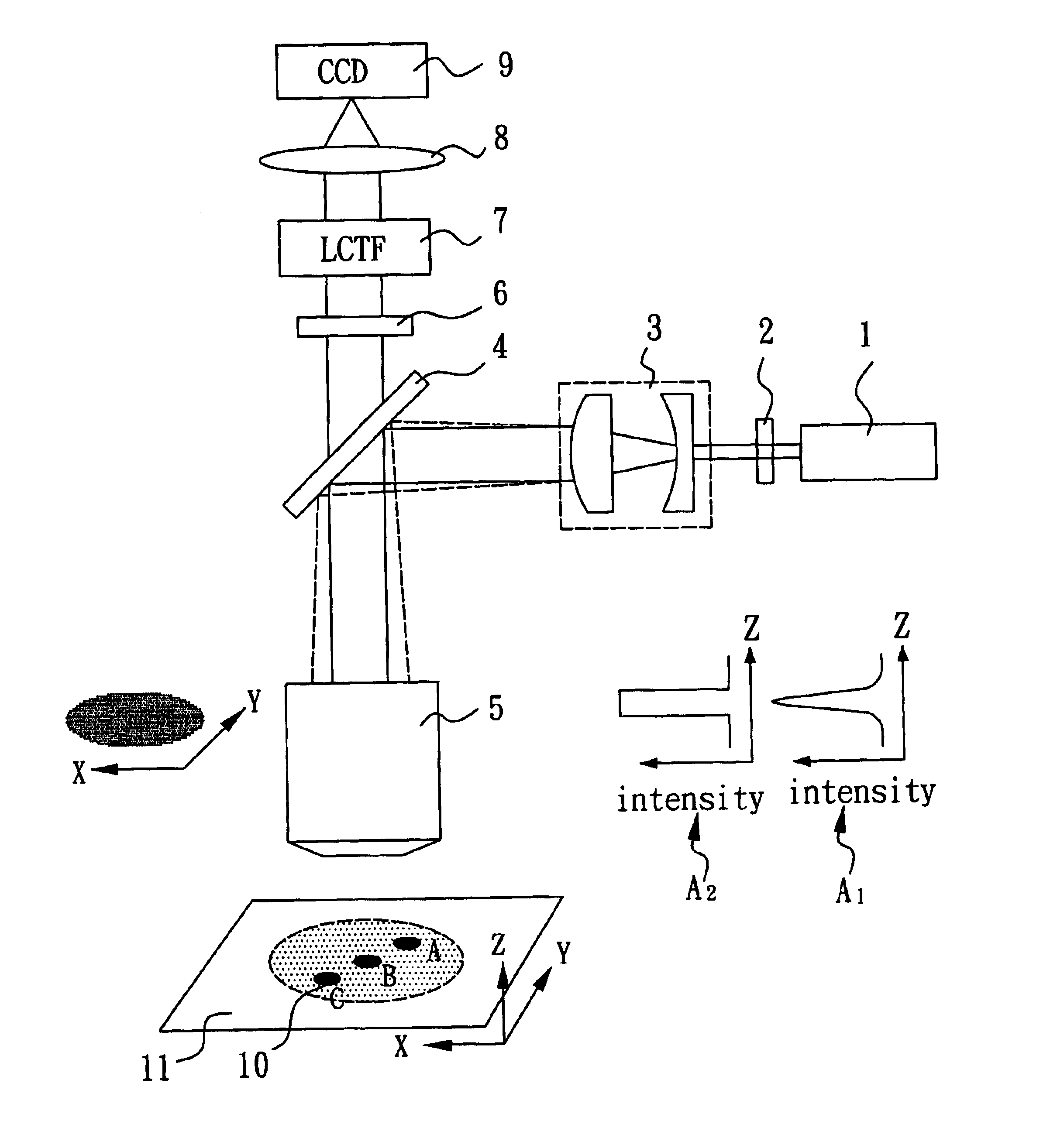
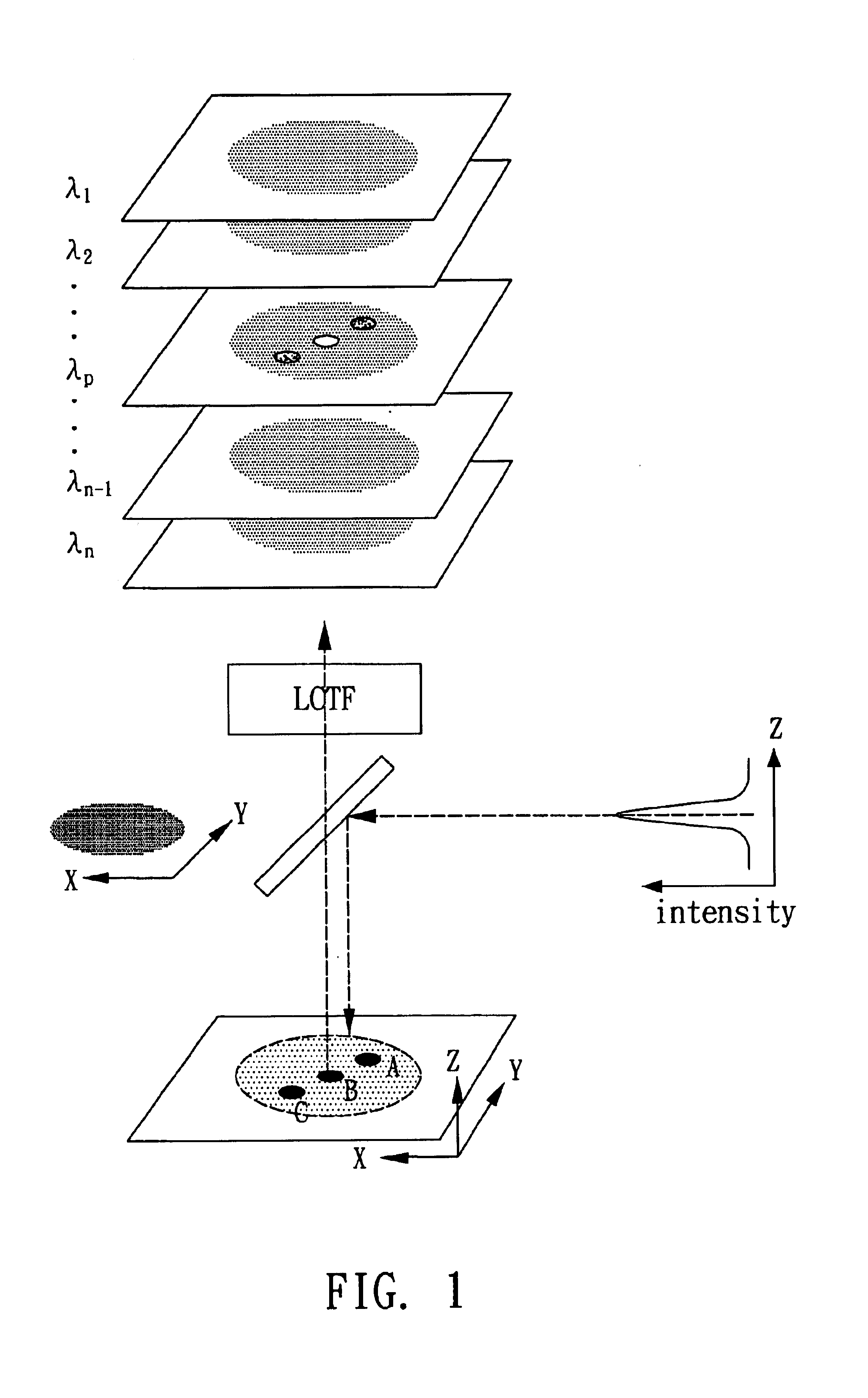
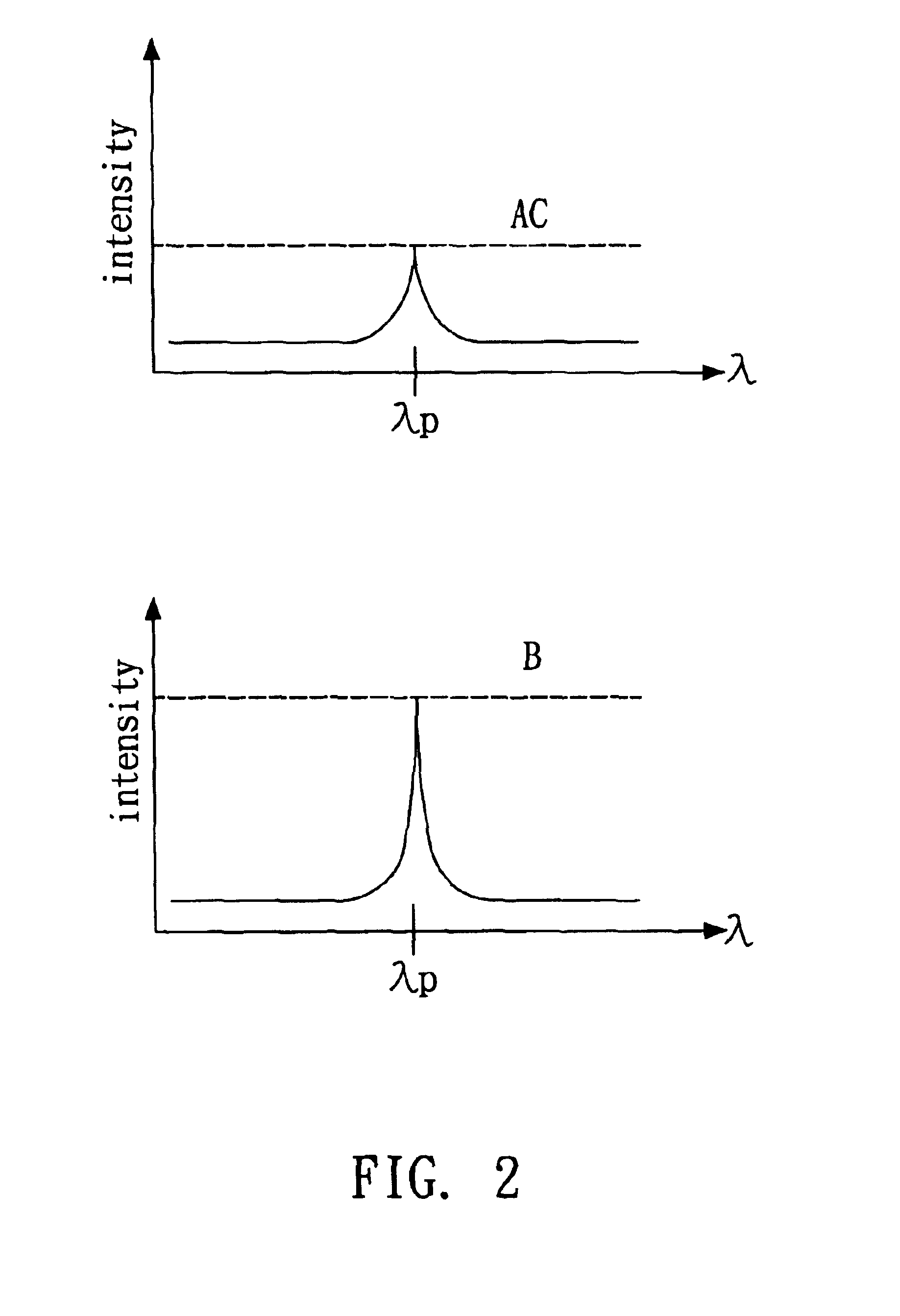
[0021]The preferred example illustrates the microscopic imaging apparatus of the present invention with the detection of polystyrene micro-spheres. With reference to FIG. 3, there is shown a microscopic imaging apparatus composed of an incident light source 1, a diffractive optical element 2, a beam expander 3, a beam-splitter 4, an objective lens 5, an optical filter 6, a tunable filter 7, an imaging lens 8, an image sensor 9, a sample 10, and a holder 11.

[0022]The incident light source 1 of the present example can be any kind of light source. Preferably, it is a light emitting diode or a laser diode, and most preferably, it is a laser. The diffractive optical element 2 is made of visible light or infrared rays passable materials. Preferably, the diffractive optical element 2 is made of quartz, polymethyl methacrylate (PMMA), or silicon according to the Scalar Diffraction Theory. The sample 10 is polystyrene micro-spheres. Preferably, the beam-splitter 4 is a dichroic mirror, the o...


PUM


Abstract

A microscopic imaging apparatus with flat-top distribution of light is disclosed, which includes an incident light source, a diffractive optical element, a beam-splitter, a tunable filter and an image sensor. The diffractive optical element receives an incident light provided by the incident light source and generates a uniform incident light. The uniform incident light illuminates a sample so that an optical signal is emitted from the sample. The optical signal passes through the beam-splitter and the filter unit to reach the image sensor for obtaining the detected image of the sample.

Description

BACKGROUND OF THE INVENTION[0001]1. Field of the Invention[0002]The present invention relates to a global imaging apparatus and, more particularly, to a microscopic imaging apparatus having a optical beam with flat-top intensity distribution, which is suitable for applications of various fields, such as fluorescence or Raman system of global imaging.[0003]2. Description of Related Art[0004]The chemical compositions, impurities, and defects existing in target materials cannot be identified and inspected by traditional optical methods, and must be measured by chemical imaging techniques. By using the laser excited electronic state spectrum or the vibration state spectrum, the chemical bonding information of sample is obtained. Among three measured methods (i.e. the point scan, line scan and global imaging) in recent chemical imaging technologies, the global imaging method has the highest image acquisition speed under the same photo-energy density (W / cm2). It is because the chemical im...

Claims


Application Information

Patent Timeline
IPC IPC(8): G02B21/06G02B5/18G02B21/08
CPCG02B21/082G02B5/1866
Inventor WANG, HAU-WEIYEH, SPRING YING-CHEUNKO, CHUN-HUNG
Owner IND TECH RES INST
Why Eureka
Try Eureka