Hybrid piezoelectric and magnetostrictive actuator

a piezoelectric and magnetostrictive actuator technology, applied in the field of electromechanical transducers, can solve the problems of reducing the transduction efficiency, the power available from down hole instruments to drive the signal transducer, and the high capacitance of piezoceramic transducers, so as to reduce the reactance load, improve the transduction efficiency, and increase the electrical efficiency

Inactive Publication Date: 2006-02-14
HALLIBURTON ENERGY SERVICES INC
View PDF16 Cites 51 Cited by
  • Summary
  • Abstract
  • Description
  • Claims
  • Application Information

AI Technical Summary

Benefits of technology

[0009]The present disclosure provides an electromechanical transducer including the combination of both a transducer with capacitive impedance and a transducer with inductive impedance coupled both electrically and mechanically. The electrical coupling of the transdu

Problems solved by technology

The power available from down hole instruments to drive the signal transducers is limited, since they are normally battery powered.
However, piezoceramic transducers are highly capacitive.
These reactive characteristics reduce the transduction efficiency, i.e. the ability to con

Method used


Image

  • Hybrid piezoelectric and magnetostrictive actuator
  • Hybrid piezoelectric and magnetostrictive actuator
  • Hybrid piezoelectric and magnetostrictive actuator

Examples


Embodiment Construction

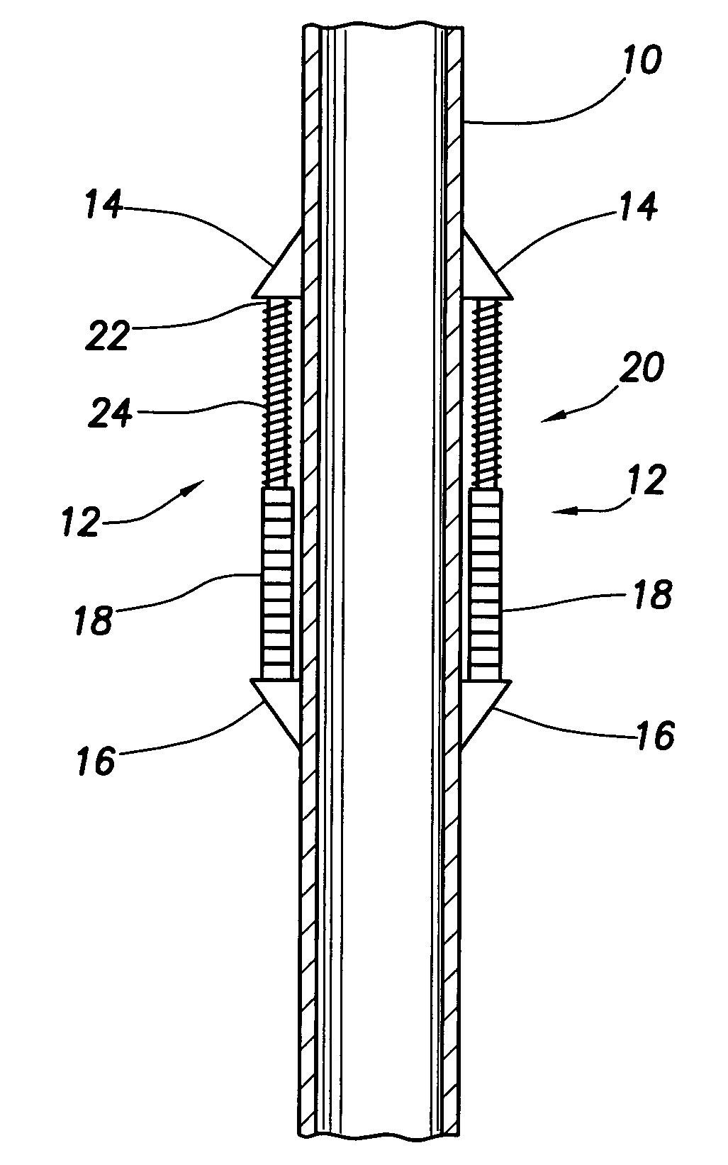
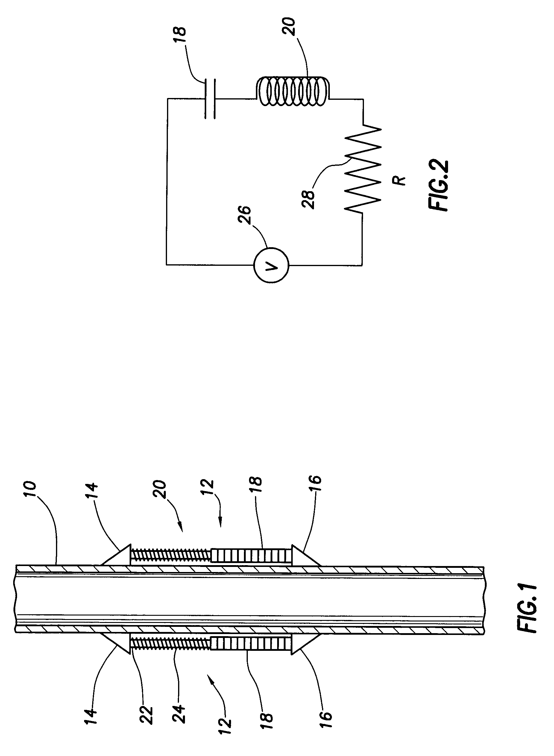
[0020]For the purposes of this disclosure, an electromechanical transducer or actuator is any device which can be driven by an electrical input and which provides a mechanical output in the form of a force or motion. Many electromechanical transducers also respond to a mechanical input, generally a force, by generating an electrical output. For purposes of the present disclosure, each transducer is considered to have an electrical connection and a mechanical connection. Each connection may be considered to be an input or an output or both, depending on whether the transducer is being used at the time to convert electrical energy into force or motion or to convert force or motion into electrical energy.

[0021]Many electromechanical transducers have a reactive impedance at their electrical connection and may be either capacitive in nature or inductive in nature. Capacitive transducers are generally driven by an electrical field, normally by applying a voltage across an electrical conne...


PUM


Abstract

An electromechanical transducer formed by an electrical and mechanical combination of a piezoelectric device and a magnetostrictive device. The two devices are electrically coupled so that their capacitive and inductive reactances approach a balance to provide an essentially resistive combined input at a selected frequency. Efficiency of circuits driving the transducer is improved. The devices are mechanically coupled so that the mechanical outputs add or reinforce each other. Two transducer pairs may be used in a two frequency telemetry system with each pair tuned to one of the frequencies for optimal reactance balancing and transduction efficiency.

Description

CROSS-REFERENCE TO RELATED APPLICATIONS[0001]Not applicable.STATEMENT REGARDING FEDERALLY SPONSORED RESEARCH OR DEVELOPMENT[0002]Not applicable.REFERENCE TO A MICROFICHE APPENDIX[0003]Not applicable.FIELD OF THE INVENTION[0004]This disclosure relates to electromechanical transducers and more particularly to the combination of a transducer with capacitive reactance and a transducer with inductive reactance in a single electrical circuit.BACKGROUND OF THE INVENTION[0005]Both piezoceramic devices and magnetostrictive devices are known to be useful as solid state actuators or electromechanical transducers which can produce mechanical motion or force in response to a driving electrical signal. These devices have been used, for example, to generate vibrations, i.e. acoustic waves, in pipes as a means of telemetering information. Such transducers are used in drilling operations to send information from down hole instruments to surface receivers. The down hole instruments generally produce ...

Claims


Application Information

Patent Timeline
IPC IPC(8): G01V3/00B06B1/06B06B1/08E21B47/14G01V1/40
CPCB06B1/06G01V1/40E21B47/14B06B1/08
Inventor FRIPP, MICHAEL L.SCHULTZ, ROGER L.
Owner HALLIBURTON ENERGY SERVICES INC
Why Eureka
Try Eureka