High intensity and high power solid state laser amplifying system and method

a laser system and laser technology, applied in the direction of laser details, excitation process/apparatus, active medium shape and construction, etc., can solve the problems of limiting and even reducing achievable power and intensity gains, inefficient or even inoperable conventional laser and amplifying systems, and achieving high power and high intensity lasers. , to achieve the effect of efficient reflection, efficient heat dissipation, and high power

Inactive Publication Date: 2006-02-14
JMAR RES
View PDF18 Cites 15 Cited by
  • Summary
  • Abstract
  • Description
  • Claims
  • Application Information

AI Technical Summary

Benefits of technology

[0011]Amplification of the input beam occurs in the pumping module that is disposed in the beam path, downstream from the two PBS's and the DPR. The pumping module includes one or more pump sources (e.g., light sources) that add optical energy to the input beam to increase its intensity and power. The one or more pump sources may include, for example, a flash pump, another type of lamp and / or a laser diode. Laser diodes can be adapted to emit in a relatively small frequency band centered around a desired frequency. Accordingly, efficiency is increased since, for example, light energy is not substantially wasted at other frequencies that might not provide effective pumping.
[0036]In an exemplary embodiment, the present invention provides that the substrates of the first and the second reflective optical mirrors include transparent materials (e.g., sapphire or diamond) characterized by high heat conductivity. Artificial analogs (e.g., cubic zirconium) can also be used. Sapphire and diamond have the physical property of rapidly diffusing localized heat. Thus, sapphire and diamond substrates help prevent the accumulation of heat that causes hot spots. In addition, both sapphire and diamond are durable materials, thus increasing the reliability of the mirrors.

Problems solved by technology

However, such high power and high intensity lasers are very hard to obtain with a high quality beam and a short pulse duration.
However, conventional laser amplifiers have design and performance aspects that limit and even reduce achievable power and intensity gains.
At high power and high intensity, heat generated by the laser pump light can create thermal optical effects and thermal stresses in laser and amplifying systems which distort the light beam, making conventional laser and amplifying systems inefficient or even inoperable.
Furthermore, the energy contained in high power and high intensity laser beams can permanently damage, if not instantly vaporize, components of conventional laser and amplifying systems.
Varying illumination intensities and thus varying indices of refraction also occur due to non-uniform energy densities resulting from laser pumping sources.
As a result, phase delays occur in the regions of higher intensity, distort the focus of the light beam and limit the gains in intensity and power.
A varying index of refraction also alters the optical path of affected portions of the beam, causing the whole beam or portions of the beam to collapse into focus points.
As a result of the B-integral effects and other sources of distortion to the light beam (such as optical imperfections in the laser path), high power and high intensity amplification in conventional laser amplifiers creates regions of heat accumulation (i.e., hot spots).
Hot spots may also form as a result of non-uniform pumping that causes varying levels of heat (e.g., heat gradients) to develop in different regions within the amplifier.
As a region heats, it further distorts the refractive index profile in the laser amplifier, leading to still greater heat accumulation.
This cycle of increasing heat and distortion continues until either the laser amplifier breaks down or destructive optical interference due to, for example, phase delays, prevents further gains in intensity and power.
For at least the above reasons, conventional laser amplifier designs are prone to hot spot formation and are limited in achievable gains in intensity and power.
Hot spot formation also enhances inefficiencies in conventional laser amplifiers since much of the amplifying laser light energy is lost as it is converted into waste heat.
Furthermore, conventional laser amplifiers are not well designed to withstand hot spots and rapidly break down under high power and high intensity amplification, requiring expensive repair and replacement of parts.
However, due to the geometry of the active laser volume and the relatively low thermal conductivity of the laser crystal rod, high temperatures and large temperature gradients may persist.

Method used


Image

  • High intensity and high power solid state laser amplifying system and method
  • High intensity and high power solid state laser amplifying system and method
  • High intensity and high power solid state laser amplifying system and method

Examples


Embodiment Construction

[0059]In accordance with the present invention, a system and a method are provided that produce high power and high intensity laser beams of high quality.

I. System and Method Overview

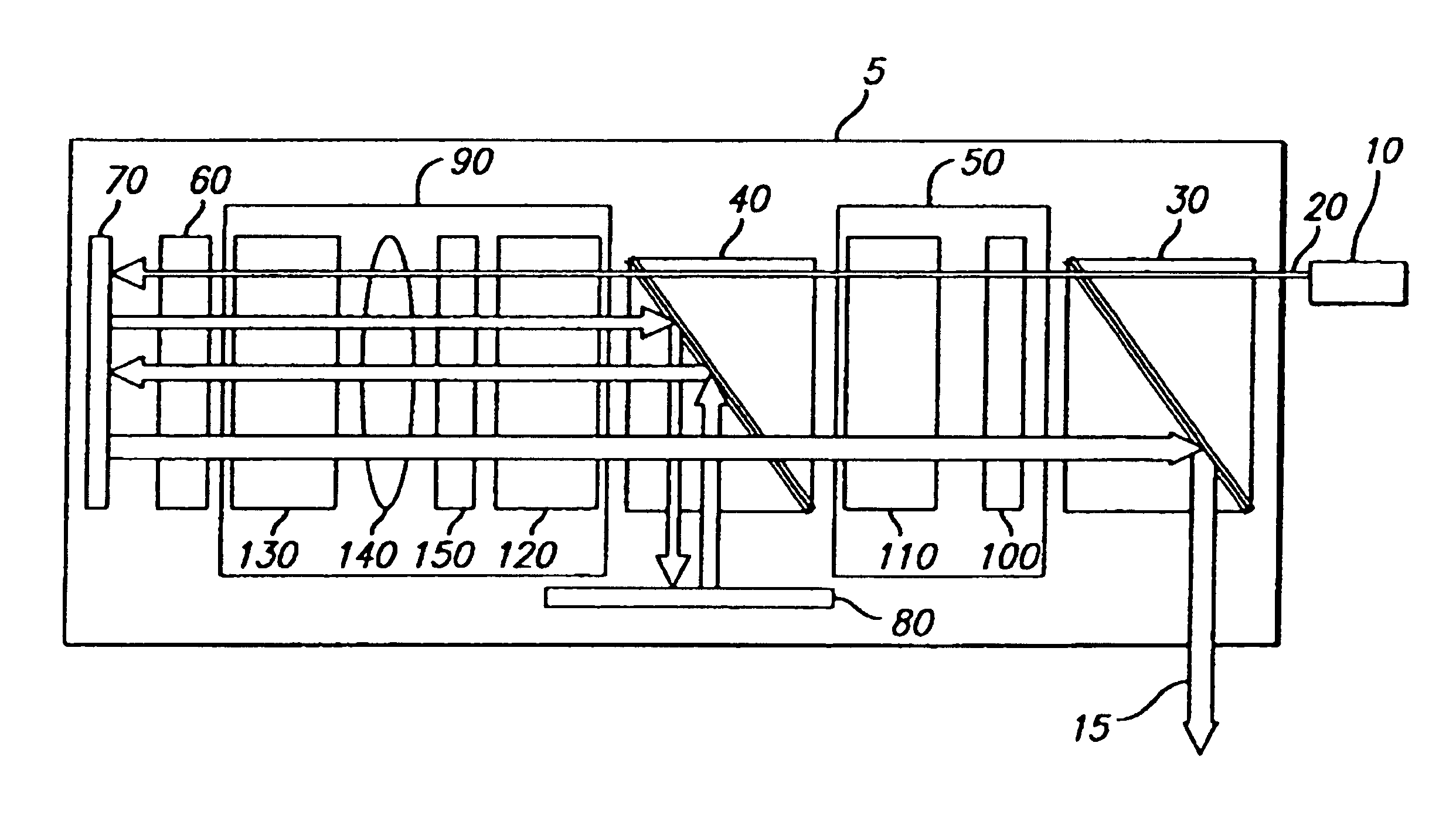
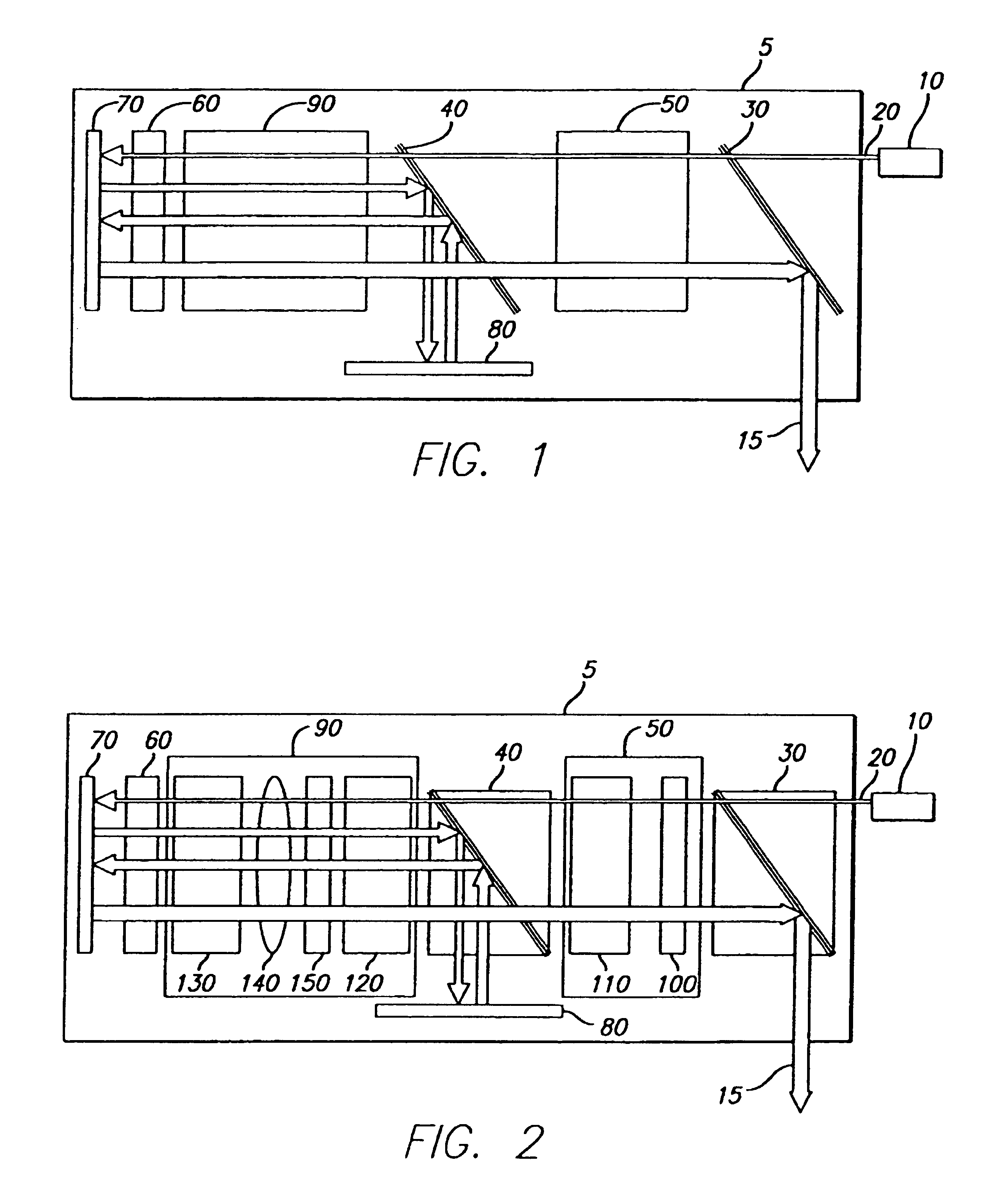
[0060]In an exemplary embodiment as illustrated in FIG. 1, the present invention provides an external laser source 10 (e.g., a master oscillator) and a laser amplifier 5. The external laser source 10 generates an input beam 20 that is amplified by the laser amplifier 5. The laser amplifier 5 includes a first polarizing beam splitter (PBS) 30, a second PBS 40, a directional polarization rotator (DPR) 50, a non-directional polarization rotator (NPR) 60, a first reflector 70, a second reflector 80 and a pumping module 90. In the illustrated embodiment, the laser amplifier 5 is configured as a four-pass optical amplifier. However, the present invention also contemplates an n-pass optical amplifier in which n is a cardinal number. Furthermore, the present invention contemplates modifications by those skilled...


PUM


Abstract

Systems and methods are provided for achieving high power and high intensity laser amplification. In a four-pass optical amplifying system, a linear polarized optical beam is directed by various optical elements four times through an optical amplifier. The optical amplifier is transversely pumped by a pumping energy source that includes laser diode arrays. The pumping module and the other optical components are provided to counteract thermal lensing effects, induced thermal birefringence effects and to achieve enhanced amplification and efficiencies.

Description

[0001]This is a continuation-in-part of U.S. patent application Ser. No. 09 / 689,539, filed Oct. 12, 2000, now abandoned entitled “Beam Correcting Laser Amplifier”, which itself is based on U.S. Provisional Patent Application Ser. No. 60 / 159,521, filed Oct. 15, 1999, entitled “Beam Correcting Laser Amplifier”. Priority is claimed to the above-identified co-pending U.S. Patent Application and to the above-identified U.S. Provisional Patent Application, both of which are incorporated herein by reference in their entirety.FIELD OF THE INVENTION[0002]The present invention generally relates to a system and a method for amplifying coherent light and, more specifically, to a system and a method for amplifying coherent light of a laser system.BACKGROUND OF THE INVENTION[0003]High power and high intensity laser systems are very desirable. However, such high power and high intensity lasers are very hard to obtain with a high quality beam and a short pulse duration.[0004]Laser amplifiers take a...

Claims


Application Information

Patent Timeline
Patent Type & Authority Patents(United States)
IPC IPC(8): H01S3/091H01S3/094H01S3/06H01S3/063H01S3/08H01S3/09H01S3/0941H01S3/23
CPCH01S3/0606H01S3/063H01S3/2341H01S3/0941H01S3/005H01S3/0064H01S3/08072H01S3/094076H01S3/1103H01S3/1106H01S3/1611H01S3/1643H01S3/2316H01S3/094084
Inventor RIEGER, HARRYCAMBEAU, SERGE
Owner JMAR RES
Why Eureka
Try Eureka