Optical measuring device

a technology of optical elements and measuring devices, applied in the direction of optical radiation measurement, instruments, spectrometry/spectrophotometry/monochromators, etc., can solve the problems of large change in the intensity of light to be emitted, the position or attitude of the optical elements, and the difficulty in relation to using a beam splitter

Active Publication Date: 2006-02-21
CANON KK
View PDF11 Cites 51 Cited by
  • Summary
  • Abstract
  • Description
  • Claims
  • Application Information

AI Technical Summary

Benefits of technology

[0020]It is accordingly an object of the present invention to provide a measuring device by which at least one of the inconveniences described above can be solved and by which the optical characteristic of an optical element (subject to be measured) can be measured very precisely regardless of a change in the radiation intensity, beam size or beam intensity distribution, for example, of a light source.

Problems solved by technology

Further, even a small change in the intensity of laser for exciting the laser plasma causes a large change in the intensity of light to be emitted.
Such change in position or attitude of the optical elements may be caused by vibration of the floor where the apparatus is mounted or by a change in environment temperature.
In the wavelength region of x-rays or EUV light, as regards the beam intensity monitor, there is a difficulty in relation to using a beam splitter such as a half mirror or a prism, for example, used in a visible light region as an element having a function for dividing a beam into plural beams.
Further, where the intensity distribution of the beam is not uniform, a change in positional relationship between the beam and the hole of the first detector or a change in the intensity distribution causes a measurement error.

Method used


Image

  • Optical measuring device
  • Optical measuring device
  • Optical measuring device

Examples


embodiment 1

[Embodiment 1]

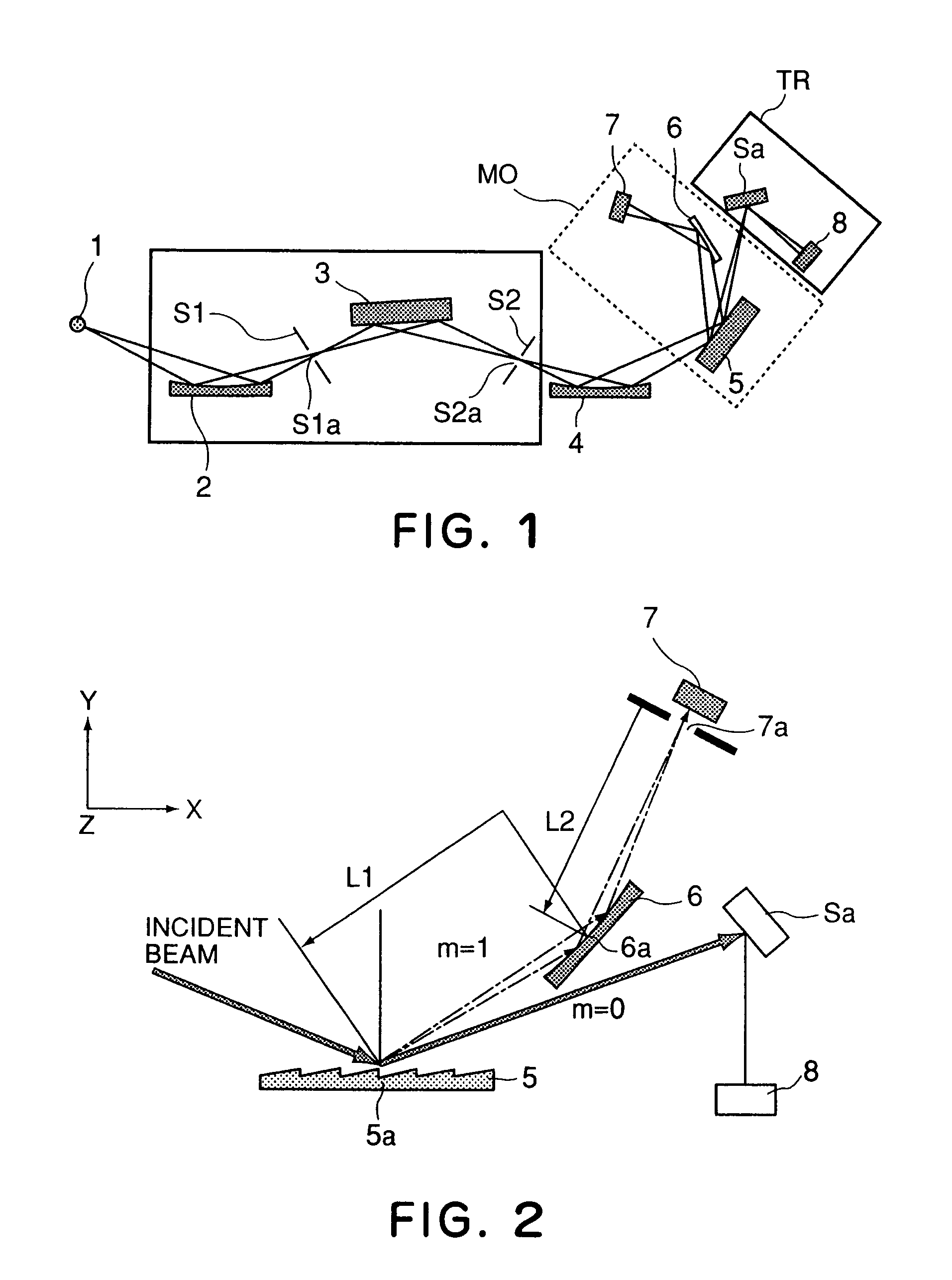
[0036]FIG. 1 is a schematic view of a main portion of a first embodiment of the present invention. FIG. 1 illustrates a measuring device for measuring the reflectivity of a sample Sa which is a multilayered film mirror in this example.

[0037]In FIG. 1, denoted at MC is a spectroscope, and denoted at MO is a beam intensity monitor (incident light intensity monitor). Denoted at TR is a sample chamber, and denoted at 1 is a light source which comprises a laser plasma light source for emitting X-rays and ultraviolet region.

[0038]Denoted at 2 is a pre-mirror for reflectively collecting light from the light source 1. It serves to direct the light toward an opening S1a of an entrance slit S1.

[0039]Denoted at 3 is a diffraction grating which functions to direct light of a predetermined wavelength, out of the light from the opening S1a of the entrance slit S1, toward and opening S2a of an exit slit S2.

[0040]Denoted at 4 is a post-mirror (curved surface reflection mirror) for dir...

embodiment 2

[Embodiment 2]

[0083]FIG. 5 is a schematic view of a main portion of a second embodiment of the present invention. FIG. 5 illustrates a device for measuring the characteristic of a sample Sa on the basis of photoelectron spectroscopy.

[0084]The photoelectron spectroscopy is a method of measuring energy spectrum of photoelectrons, emitted by external photoelectric effect in response to irradiating a sample Sa placed in a vacuum with high-energy monochromatic light. FIG. 5 illustrates a main portion of a measuring system of a photoelectron spectroscope MC. As major components, the device comprises a plasma light source 1, a spectroscope MC, a rotary stage, and a photoelectron energy analyzer TR.

[0085]Light from the light source 1 is made into monochromatic light by the spectroscope MC, under the structure similar to that of the reflectivity measuring device of the first embodiment, and the light is projected upon the sample Sa through an incident light intensity monitor MO. The light em...


PUM

PropertyMeasurementUnit
diameteraaaaaaaaaa
incidence angleaaaaaaaaaa
reflectivityaaaaaaaaaa

Abstract

The present invention provides a measuring device by which, even if a radiation intensity from a light source, a beam size or a beam intensity distribution of the light source changes, an optical characteristic of an optical element to be measured can be measured very precisely. In a measuring device according to the present invention, to this end, light from a light source is diffracted by a diffracting grating to thereby resolve the same into plural light beams, and by using different light beams, the object to be measured is measured and the intensity of incident light from the light source is measured. With this structure, even if the light from the light source changes, the intensity of the light from the light source is specified concurrently, and therefore, the optical characteristic of the object to be measured can be measured very accurately.

Description

FIELD OF THE INVENTION AND RELATED ART[0001]This invention relates generally to a measuring device and, more particularly, to a measuring device suitable to measurement of an optical characteristic such as a reflectivity or transmissivity, for example, of an optical element to be used with X-rays, soft X-rays, or EUV light (extreme ultraviolet light), for example.[0002]Recently, many proposals have bean made in regard to semiconductor device manufacturing apparatuses designed to be used with light of extremely short wavelength such as X rays, soft X-rays, or EUV light, for example. In order to meet this, many proposals have been made in respect to measuring devices for measuring optical characteristics of optical elements to be used in such manufacturing apparatuses.[0003]As an example of measuring device for evaluating the property (physical or chemical property) of a sample by irradiating the sample with soft X rays, there is a measuring device for measuring the reflectivity of a ...

Claims


Application Information

Patent Timeline
Patent Type & Authority Patents(United States)
IPC IPC(8): G01T1/36G01N23/20G01J1/00G01J3/10
CPCG01J1/4257G01N23/20G01J3/12G01N2223/611G21K1/06G01N2223/052
Inventor MIYAKE, AKIRAMASAKI, FUMITARO
Owner CANON KK
Why Eureka
Try Eureka