Method for manufacturing a flow cell

a flow cell and manufacturing technology, applied in the direction of manufacturing tools, surface layering apparatus, instruments, etc., can solve the problems of reducing the light conductivity value, increasing noise, and limiting the detection limi

Inactive Publication Date: 2006-02-28
AGILENT TECH INC
View PDF11 Cites 13 Cited by
  • Summary
  • Abstract
  • Description
  • Claims
  • Application Information

AI Technical Summary

Benefits of technology

[0010]According to an embodiment of the invention the tool which is drawn through the interior of the tube is heated, thus supporting the forming process. Alternatively or additionally, the tube material may also be heated.
[0011]In a preferred embodiment of the invention, an adapter is fixed to each of the two ends of the cell housing for closing the flow cell at the inlet and at the outlet. The adapters may comprise sample inlet and outlet channels, respectively, as well as pre-mounted optical fibers for introducing light into the flow cell and for conducting the light modified by the sample to a detection element.
[0012]The tube may be widened at the two end regions of the flow cell housing by a stamping tool such that it has the shape of a trumpet or funnel at these ends, and the adapter can then be used to jam the funnel-like parts between the cell housing and the adapters.

Problems solved by technology

Unfortunately, these are conflicting requirements since in the mentioned flow cells an increase of the sensitivity at constant cell volume leads to a reduction of the light conductivity value which in turn increases the noise and thus limits the detection limit.
A shrinking step has disadvantages, because any inhomogeneities in the shrinking material lead to bending of the Teflon AF tube which causes a deterioration of the light throughput.
In addition, the known process is complicated and costly because measures have to be taken to prevent damage of the Teflon AF layer when removing the mandrel and to ensure that the Teflon layer remains stable after removal of the mandrel.
This, however, has the disadvantage that due to the direction of inflow and the mass of the molding material the soft Teflon AF tube may be deformed during the molding step, particularly with long cells.
A consequence is that the optical properties, in particular the total reflection properties, are impaired.
The result is the loss of light and thus unwanted influences on the signal, for example an increase in the sensitivity to refractive index changes.

Method used


Image

  • Method for manufacturing a flow cell
  • Method for manufacturing a flow cell
  • Method for manufacturing a flow cell

Examples


Embodiment Construction

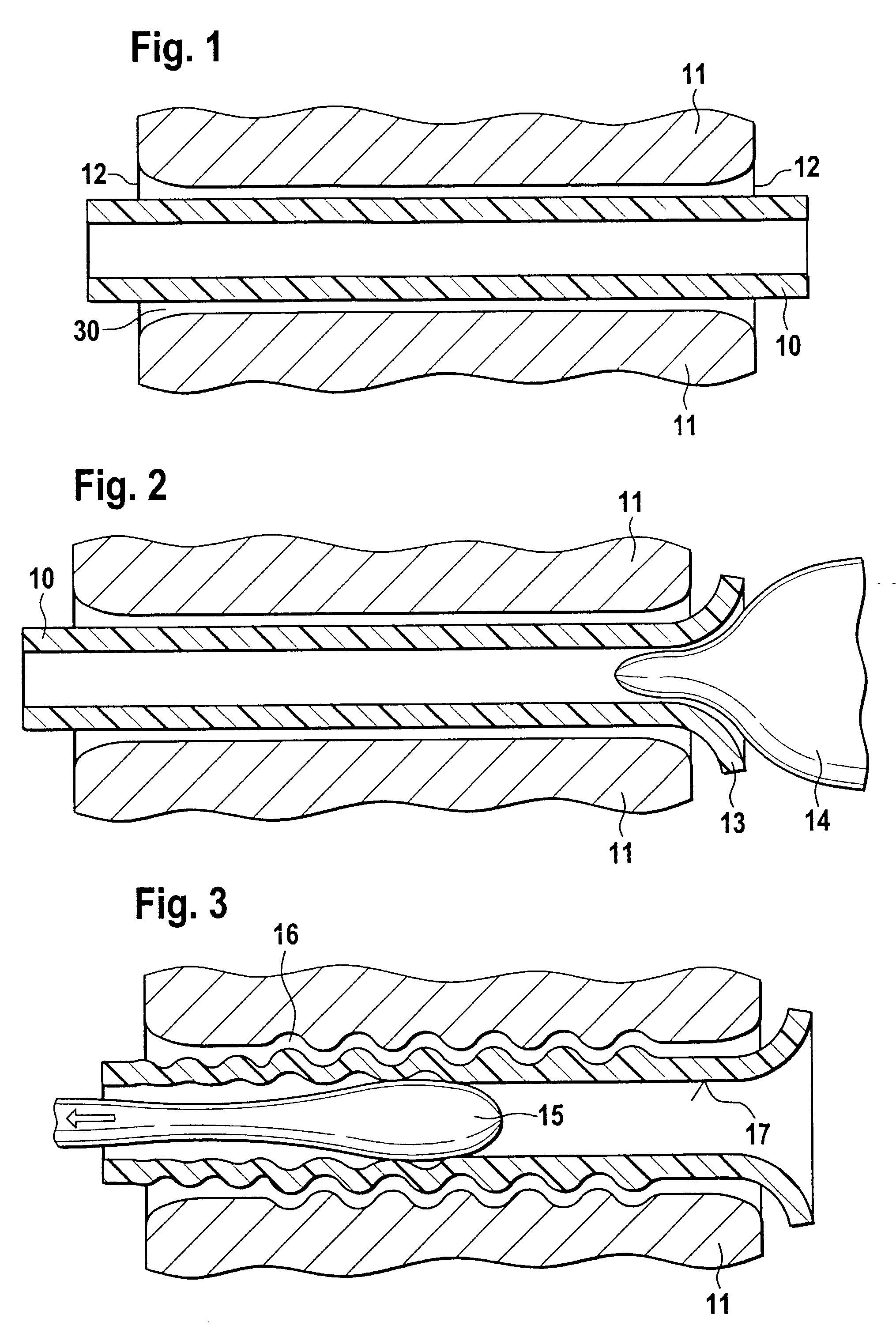
[0019]As shown in FIG. 1, a tube 10 of Teflon AF is pushed into a cylindrical bore 30 of a cell housing 11. The housing 11 typically is a steel capillary and has machined end regions 12. The inner diameter of the housing, i. The diameter of the bore 30, is slightly larger than the outer diameter of the tube 10 such that it is just possible to insert the tube. Extruded Teflon AF tubes are available as semi-finished products from DuPont with an inner diameter of about 0.5 mm and an outer diameter of about 0.7 mm. The tube 10 projects from both ends of the housing 11 by about the same amount.

[0020]The housing 11 and one end of the projecting tube 10 are fixed with a special device (not shown). Then, as shown in FIG. 2, a heated stamping tool 14 is used to form the other end of the tube to a trumpet or funnel shape 13. During this forming step the housing 11 serves as support, wherein the end regions 12 of the housing have the desired trumpet shape.

[0021]In the next step, illustrated in...


PUM

PropertyMeasurementUnit
outer diameteraaaaaaaaaa
thicknessesaaaaaaaaaa

Abstract

A method of manufacturing a flow cell with a cell housing having a bore for the passage of sample, and with an inner layer of a totally reflecting polymer material for guiding radiation through the bore for the analysis of the sample, comprises the steps of: a) providing a tube of the polymer material in the bore of the cell housing, and b) applying a force on the walls of the tube from the interior of the tube for pressing the walls of the tube against the cell housing. The force may be applied by any suitable means, for example by drawing a mandrel through the interior of the tube, or by using pressurized gas or liquid. The resulting flow cell has a smooth inner surface with improved optical properties.

Description

[0001]The invention relates to a method for manufacturing a flow cell with an inner layer of a totally reflecting polymer material for guiding radiation through a bore of the flow cell.BACKGROUND OF THE INVENTION[0002]Flow cells are typically used in optical detectors for measuring the optical characteristics of a sample liquid flowing through the flow cell. Such detectors with the corresponding flow cell are used, for example, in liquid chromatography, or in capillary electrochromatography, or capillary electrophoresis, for determining the identity and concentration of sample substances. Ultraviolet (UV) and visible (Vis) light detectors wherein the absorbance of a sample in the flow cell is measured are frequently used for the mentioned separation techniques. Known flow cells are typically made of steel or quartz and have a cylindrical bore through which the liquid flows and through which light for analyzing the sample is directed.[0003]It is important that a detector has: a) a hi...

Claims


Application Information

Patent Timeline
Patent Type & Authority Patents(United States)
IPC IPC(8): B29D11/00G01N21/05
CPCG01N21/05G01N2021/0346
Inventor MUELLER, JOCHENMUELLER, BENO
Owner AGILENT TECH INC
Why Eureka
Try Eureka