Manufacture of MEMS structures in sealed cavity using dry-release MEMS device encapsulation

a technology of mems device and sealing cavity, which is applied in the direction of fluid speed measurement, acceleration measurement using interia forces, instruments, etc., can solve the problems of reducing the complexity of mems microstructures that can be released, affecting the performance of flexible structures, and affecting the stability of flexible structures

Inactive Publication Date: 2006-03-07
CYMATICS LAB CORP
View PDF12 Cites 297 Cited by
  • Summary
  • Abstract
  • Description
  • Claims
  • Application Information

AI Technical Summary

Problems solved by technology

However, one unfortunate problem when working with a “wet” etchant is that the surface tension generated as the liquid evaporates can be strong enough to bend or even break delicate MEMS microstructures.
Therefore, the use of liquid etching agents severely limits the complexity of the MEMS microstructures that can be released from ...

Method used


Image

  • Manufacture of MEMS structures in sealed cavity using dry-release MEMS device encapsulation
  • Manufacture of MEMS structures in sealed cavity using dry-release MEMS device encapsulation
  • Manufacture of MEMS structures in sealed cavity using dry-release MEMS device encapsulation

Examples


Embodiment Construction

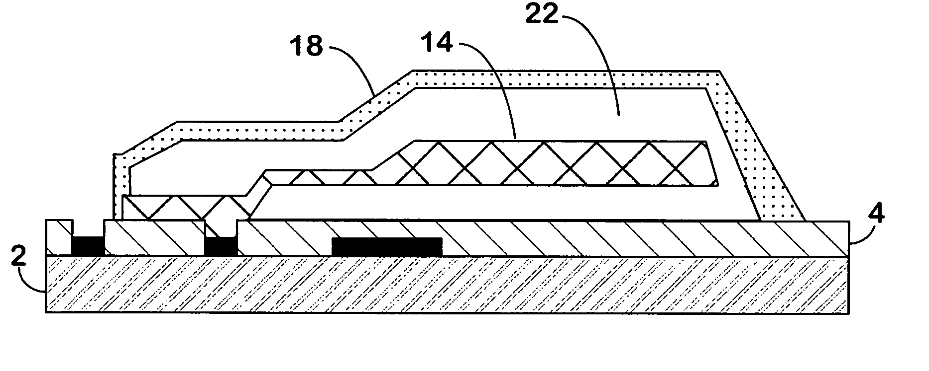
[0018]In general, the invention disclosed refers to gas phase release of any number of microstructure layers whose movement is independent or coupled and which are encapsulated in the thin film seal layer. However, in order to explain the invention, one specific embodiment will be described in detail below, namely a microstructure that can be utilized as a Z-axis accelerometer. This device consists of a paddle shaped MEMS microstructure anchored at one point by a thin supporting member such that it can move vertically within the sealed cavity.

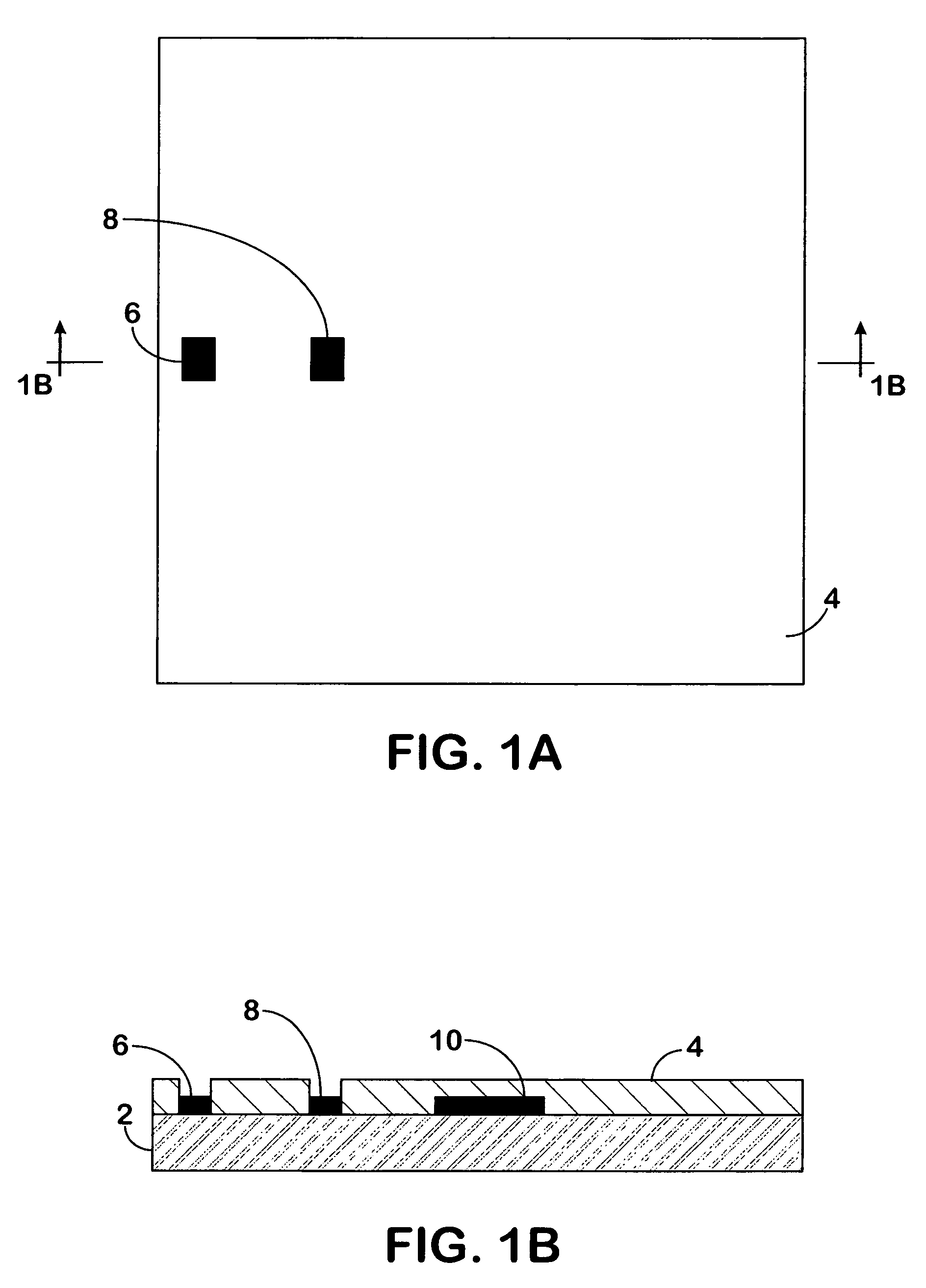
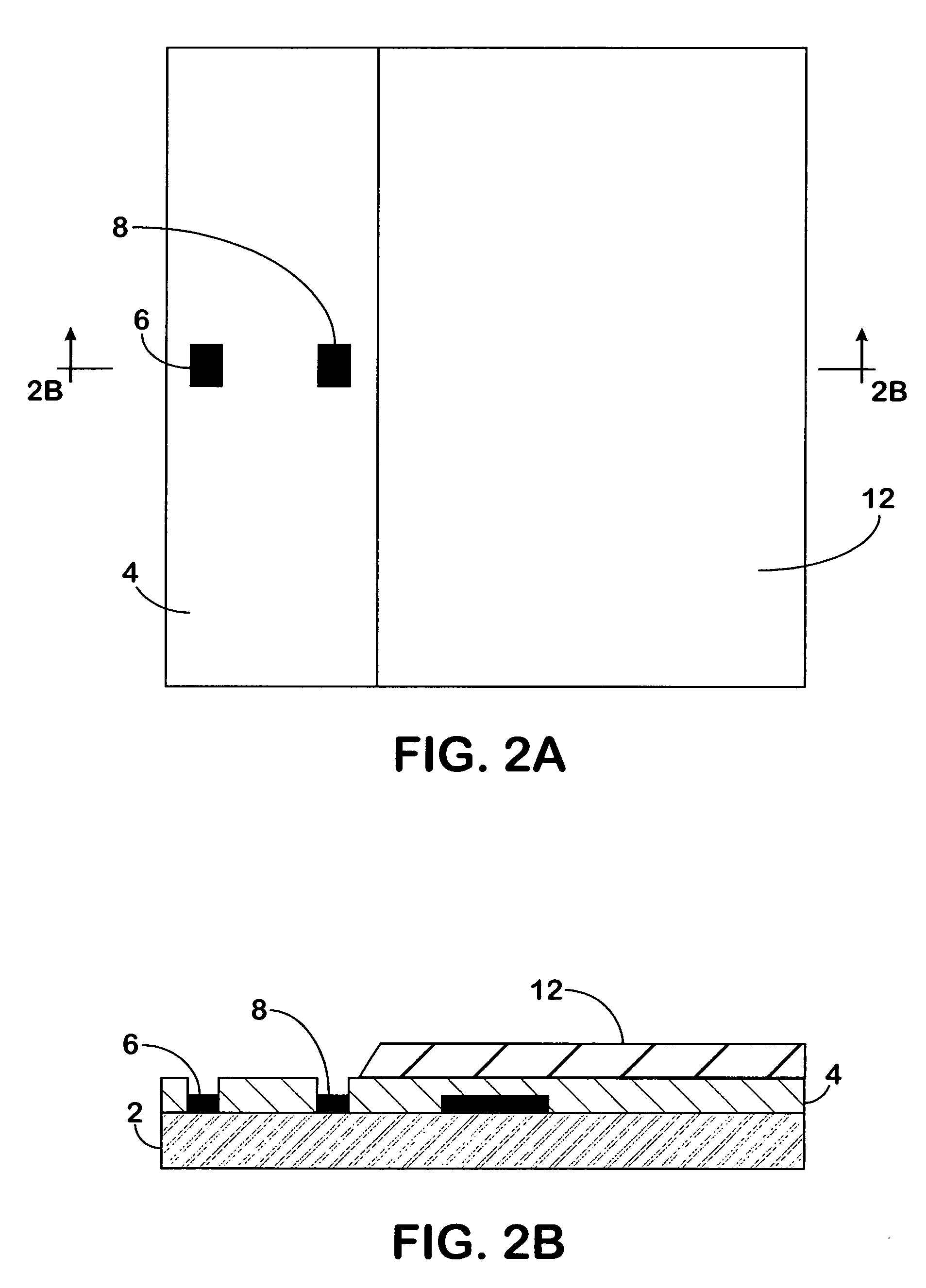
[0019]FIGS. 1–9 illustrate the sequence of steps comprising the fabrication of the proposed encapsulated integrated microstructure CMOS process. We start by obtaining or fabricating a silicon CMOS wafer 2 coated with a layer of silicon nitride 4 and having metal pads interfacing to the original CMOS integrated circuit 6, 8 and 10 present as shown. Openings appear in the silicon nitride layer 4 to allow access to metal pads 6 and 8. In the prefe...


PUM


Abstract

The disclosed fabrication methodology addresses the problem of creating low-cost micro-electro-mechanical devices and systems, and, in particular, addresses the problem of delicate microstructures being damaged by the surface tension created as a wet etchant evaporates. This disclosure demonstrates a method for employing a dry plasma etch process to release encapsulated microelectromechanical components.

Description

FIELD OF THE INVENTION[0001]This invention relates to the process of manufacturing micro-electro-mechanical systems (MEMS), and, in particular, to MEMS devices having sealed cavities or encapsulated movable parts.BACKGROUND OF THE INVENTION[0002]This disclosure builds on prior art describing a method for constructing micro-electro-mechanical systems by using multiple sacrificial thin film layers removed using a liquid etch.[0003]It is known in the prior art to create sealed cavities on an integrated circuit for a variety of applications, for example, as a speaker or microphone. It is also known to encapsulate movable mechanical components on an integrated circuit within a sealed cavity. The encapsulation of micro-electro-mechanical structures in a sealed cavity is desirable for several reasons. First, the tolerance of the structures to ambient conditions, such as high humidity, is greatly improved. Second, the dicing and packaging of the MEMS devices is greatly facilitated. Third, w...

Claims


Application Information

Patent Timeline
IPC IPC(8): H01L21/3065B81B3/00B81B7/00G01P1/02G01P15/08
CPCB81B7/0077B81C1/00476B81C1/00936G01P15/0802G01P1/023B81B2203/0315B81C2201/0132B81C2203/0136B81C2201/0109G01P2015/0828
Inventor CARLEY, L. RICHARD
Owner CYMATICS LAB CORP
Why Eureka
Try Eureka