Oversampling clock recovery having a high follow-up character using a few clock signals

a clock signal and recovery circuit technology, applied in pulse manipulation, pulse technique, synchronisation signal speed/phase control, etc., can solve the problems of difficult to make oscillation frequency, difficult to meet the request of high-speed in clock recovery circuit and phase locked loop, and difficult to cope with a further high-speed of data transmission. , the effect of high follow-up character and high resolution

Inactive Publication Date: 2006-03-07
RENESAS ELECTRONICS CORP
View PDF9 Cites 57 Cited by
  • Summary
  • Abstract
  • Description
  • Claims
  • Application Information

AI Technical Summary

Benefits of technology

[0008]More specifically, it is another object of this invention to provide an oversampling clock recovery method and an oversampling clock recovery circuit which are capable of realizing a high follow-up character for sufficiently following variations in a speed of data at a relatively small phase number of clock signals.
[0009]It is still another object of this invention to provide an oversampling clock recovery method and an oversampling clock recovery circuit which are capable of generating clock sign...

Problems solved by technology

It is difficult to meet the request of the high-speed in the clock recovery circuit and the phase locked loop (PLL).
For example, it is not easy to make an oscillation frequency of a voltage controlled oscillator (VCO) included in the phase locked loop (PLL)...

Method used


Image

  • Oversampling clock recovery having a high follow-up character using a few clock signals
  • Oversampling clock recovery having a high follow-up character using a few clock signals
  • Oversampling clock recovery having a high follow-up character using a few clock signals

Examples


first embodiment

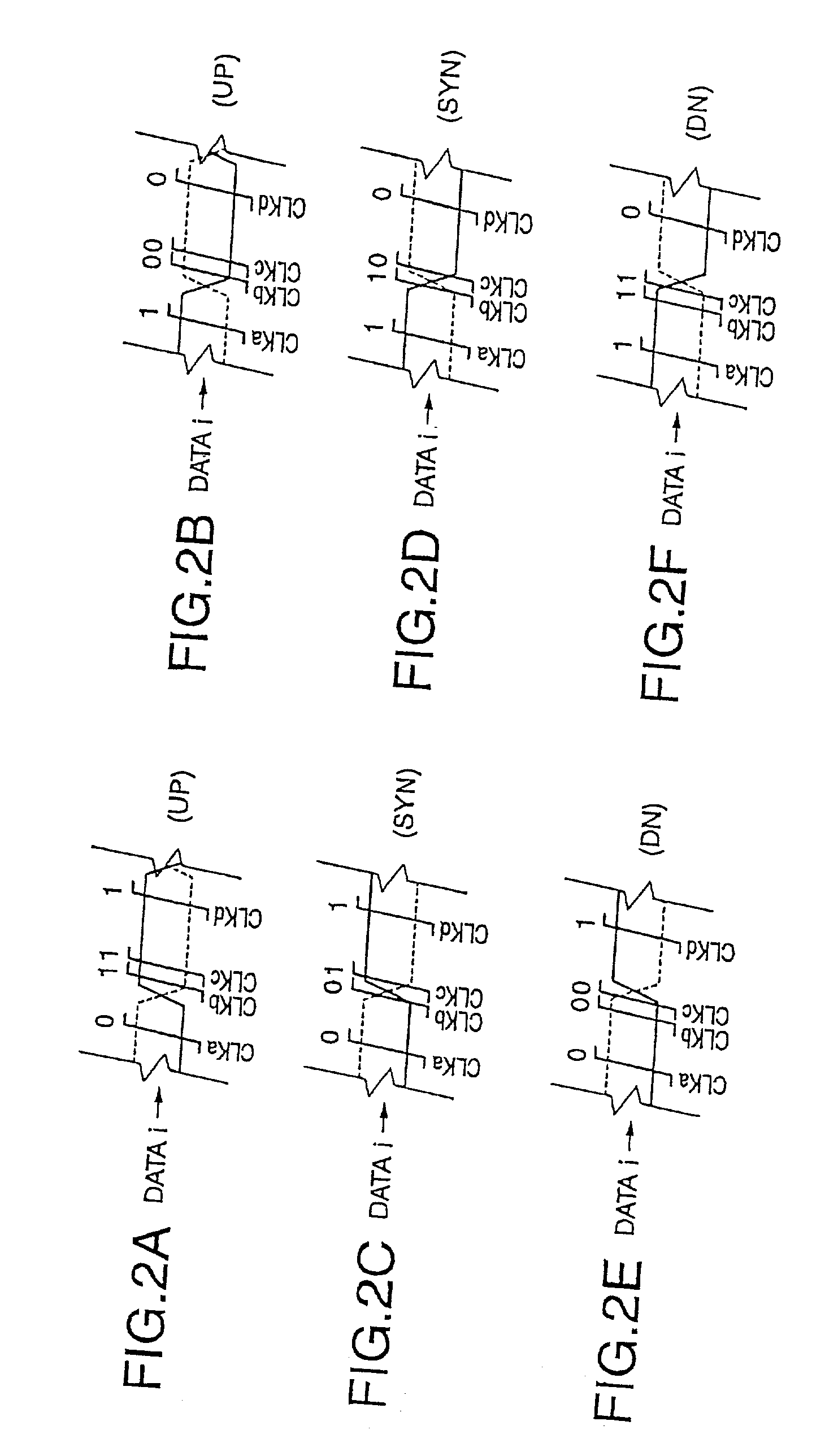
[0064]Referring to FIGS. 2A, 2B, 2C, 2D, 2E, and 2F, the description will proceed to an oversampling clock recovery method according to a first embodiment of this invention. FIGS. 2A through 2F are time charts showing waveforms for use in describing the oversampling clock recovery method according to the first embodiment of this invention.

[0065]The illustrated oversampling clock recovery method generates three-phase clock signals CLKa, CLKb, and CLKc having non-uniform intervals for one bit of an input data i. In addition, clock signals CLKb, CLKc, and CLKd also are three-phase clock signals having non-uniform intervals for the one bit of the input data i. Four-phase clock signals CLKa, CLKb, and CLKc, and CLKd are called first through fourth clock signals, respectively. The oversampling clock recovery method comprises the steps of sampling the input data i using the four-phase clock signals CLKa, CLKb, CLKc, and CLKd, of detecting phase differences between the input data i and the ...

second embodiment

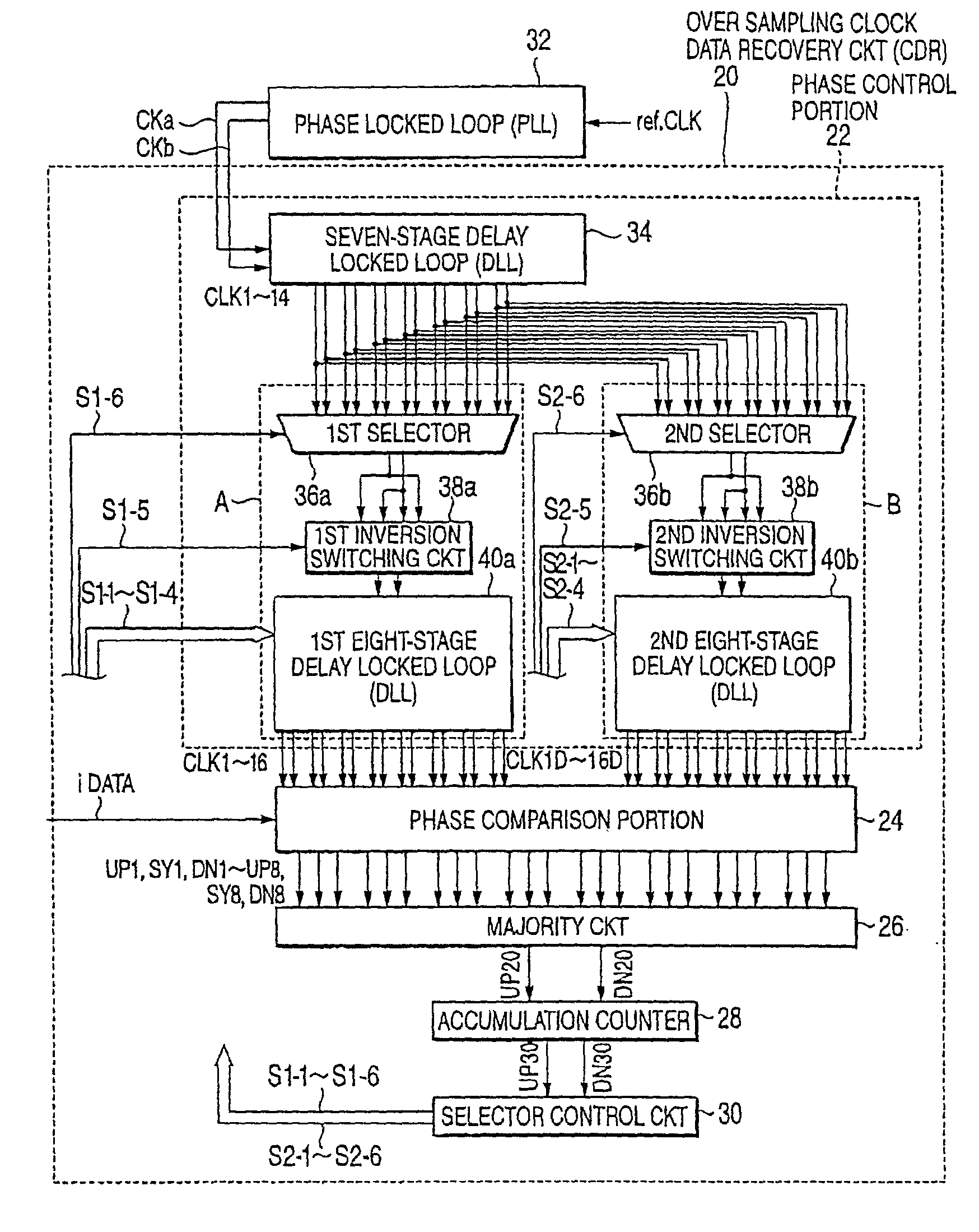
[0078]Referring to FIGS. 3 through 10, the description will proceed to an oversampling clock data recovery circuit according to a second embodiment of this invention. FIG. 3 is a block diagram showing the oversampling clock data recovery circuit according to the second embodiment of this invention.

[0079]The first embodiment does not describe about realization of circuitry. The illustrated oversampling clock data recovery circuit (which may be called “CDR” for short) is a circuit for implementing the oversampling clock recovery method of the first embodiment. In the second embodiment, description exemplifies a case of dealing with an 8-bit serial input data having a data rate of 2.5 Gbps and a differential clock signal having a clock frequency of 312.5 MHz (a period of 3200 ps).

[0080]The oversampling clock recovery circuit according to the second embodiment generates, as first multi-phase clock signals, fourteen multi-phase clock signals CK1 to CCK14, as second multi-phase clock sign...

third embodiment

[0224]Referring to FIGS. 11A, 11B, 11C, 11D, 11E, 11F, 11F, and 11H, the description will proceed to an oversampling clock recovery method according to a third embodiment of this invention. FIGS. 11A to 11H are time charts showing waveform for use in describing the oversampling clock recovery method according to the third embodiment of this invention.

[0225]The illustrated oversampling clock recovery method is different from the oversampling clock recovery method according to the first embodiment and detects lag / lead of clock signals in reference with an input data i by sampling the input data using six-phase clock signals CLKe, CLKf, CLKg, CLKh, CLKi, and CLKj where four leading clock edges correspond to one bit of the input data i. The six-phase clock signals CLKe to CLKj are called first through sixth clock signals, respectively.

[0226]A phase interval between the first clock signal CLKe and the fifth clock signal CKLi is equal to a length of the one bit of the input data i. The fi...


PUM


Abstract

An oversampling clock recovery method according to this invention generates non-uniform three-phase clock signals CLKa, CLKb, and CLKc having non-uniform intervals for one bit of an input data i and controls phases of the clock signals so that either phase of two edges of two-phase clock signals CLKb and CLKc having a relatively narrower interval of 57 ps synchronizes with a phase of a transition point of the input data i. By changing clock signals to be phase-locked in three delay locked loops (DLLs), a phase interval of 57 ps is formed.

Description

BACKGROUND OF THE INVENTION[0001]This invention relates to an oversampling clock recovery method.[0002]In recent years, a high-speed protocol has been proposed in data transmission. For this purpose, high speed is requested in a clock recovery circuit and a phase locked loop (PLL). The clock recovery circuit carries out extraction of a clock signal from data transmitted in a high-speed transmission. The phase locked loop (PLL) frequency synchronizes a clock signal used in a circuit with a transmitted clock signal.[0003]Various analog type clock recovery circuits has been proposed. One of them carries out a phase-comparison using a one-phase clock signal by making one leading edge of the clock signal correspond to one bit of data. Inasmuch as it is necessary in this circuit to make a data rate equal to a clock frequency, the clock frequency must be made a high-frequency wave of a level of gigahertz (GHz) when the data rate becomes the level of giga bit per second (Gbps). It is diffic...

Claims


Application Information

Patent Timeline
IPC IPC(8): H04L7/04H03D3/24H03K5/15H03L7/07H03L7/081H03L7/087H03L7/091H03L7/099H04L7/033
CPCH03L7/07H03L7/0814H04L7/0337H03L7/091H03L7/0995H03L7/087H03L7/0816
Inventor NAKAMURA, SATOSHI
Owner RENESAS ELECTRONICS CORP
Why Eureka
Try Eureka