Shaft/hub unit for wind turbine rotor

a technology for wind turbines and hub units, which is applied in the direction of propellers, propulsive elements, water-acting propulsive elements, etc., can solve the problems of affecting the performance of the component, the need to screw together individual components, and the negative effect of component costs, etc., to achieve the effect of reducing the weight of the component, and reducing the cost of the componen

Inactive Publication Date: 2006-03-14
AERODYN ENG GMBH
View PDF7 Cites 17 Cited by
  • Summary
  • Abstract
  • Description
  • Claims
  • Application Information

AI Technical Summary

Benefits of technology

[0010]The blade or blade bearing connection can be constructed as metallic inserts integrated into the rotor hub laminate. The rotor bearing seat can be constructed as a bush integrated into the rotor shaft laminate. Thus, the invention proposes a component combination in which the individual components, rotor hub and rotor shaft, are combined into an integral component made from bonded fiber fabrics. The combination of the two individual components into an integral component and the use of bonded fiber fabrics lead to numerous technical and economic advantages.
[0011]Compared with the conventionally used metallic materials, bonded fiber fabrics have a very high specific strength and rigidity so that whilst fulfilling the same requirements a lighter weight component can be implemented. Bonded fiber fabrics are materials which comprise one or more fiber types and a resin matrix with or without additives. A particular advantage of using bonded fiber fabrics is that random fibers with random orientation can be used, so that the direction-controlled, mechanical characteristics of the mat...

Problems solved by technology

One disadvantage is that, as a result of the characteristics of the materials used, the individual components are very heavy, which makes component assembly more difficult.
A further disadvantage is the need of screwing together the individual componen...

Method used


Image

  • Shaft/hub unit for wind turbine rotor
  • Shaft/hub unit for wind turbine rotor

Examples


Embodiment Construction

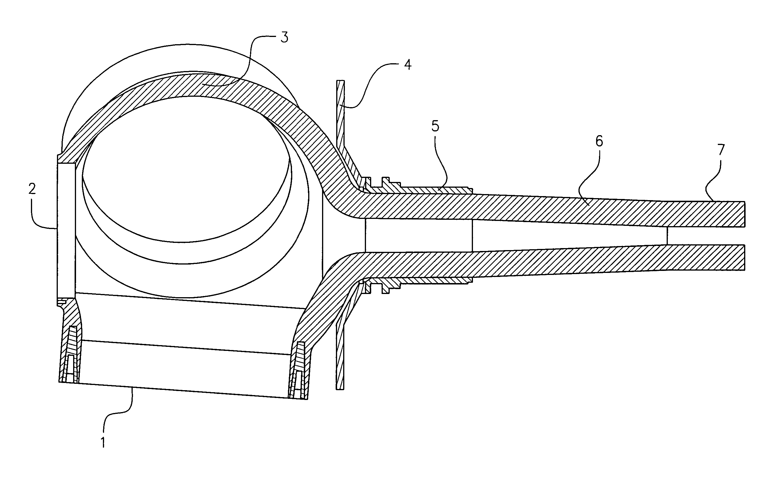
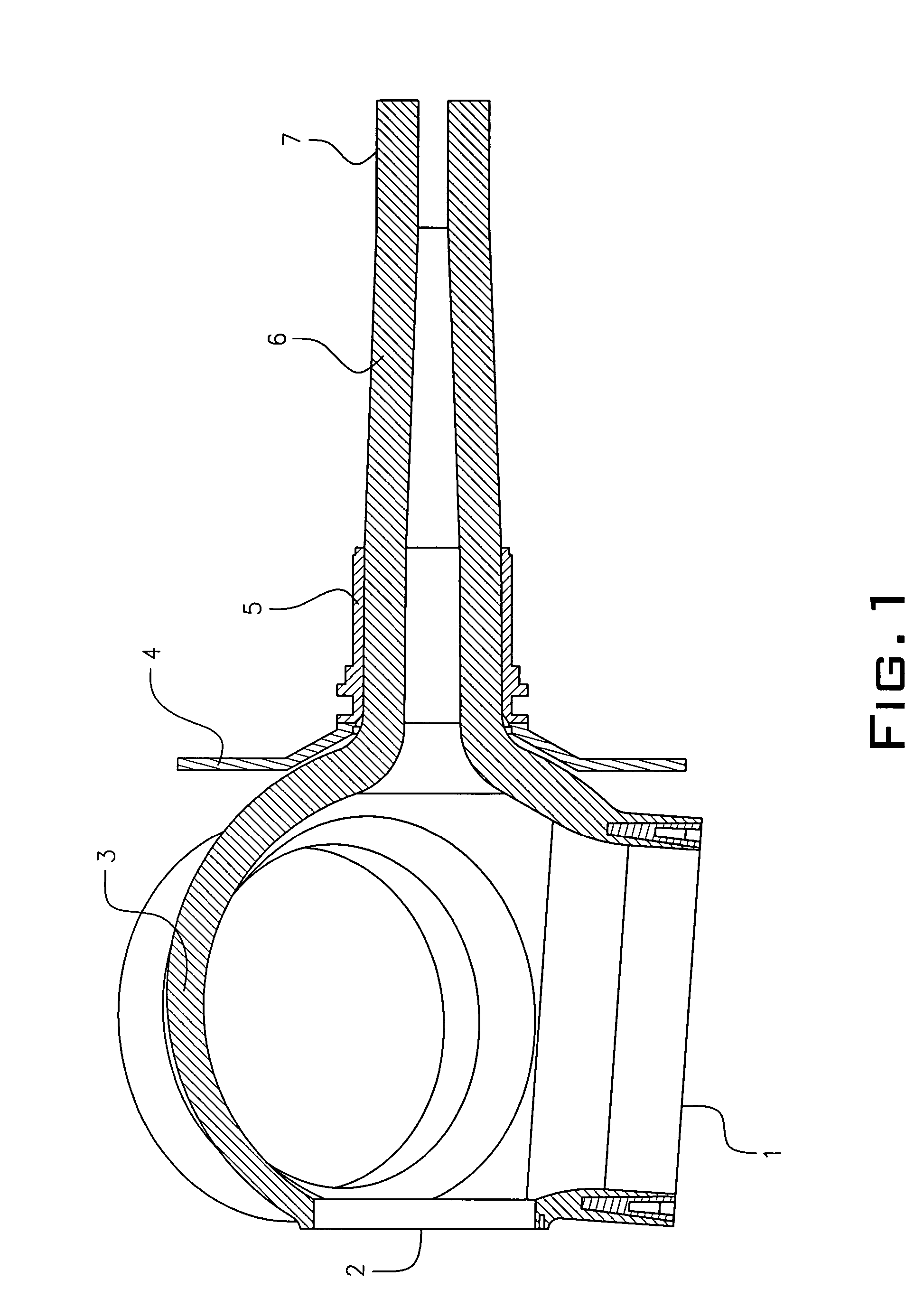
[0017]The component body comprising the rotor hub 3 and rotor shaft 6 is made from bonded fiber fabric. The blade or blade bearing connection 1 is used for joining the rotor blade directly or via a bearing to the hub 3. This junction or connection comprises metallic inserts with blind hole threads integrated into the laminate of the rotor hub 3. In the front of the rotor hub 3 is provided an access hole 2 giving access to the interior of the rotor hub 3. A rotor locking disk 4 is used for locking the wind energy plant rotor during maintenance and is connected by a bonded or screwed joint directly to the rotor hub 3 or rotor bearing seat 5. The rotor locking disk 4 is made either from a metallic material or a bonded fiber fabric. The rotor bearing seat 5 is used for receiving the rotor bearing and is constructed in the form of a bush made from metal, plastic or a bonded fiber fabric. This bush is either integrated into the laminate of the rotor shaft 6, or connected from the outside ...


PUM


Abstract

A rotor shaft/hub unit for a wind energy plant with a rotor shaft provided with a rotor bearing seat which is connected to a rotor hub provided with a blade or blade bearing connection, the rotor hub and rotor shaft are manufactured in one piece from bonded fiber fabrics.

Description

PRIOR APPLICATIONS[0001]This is a §371 National Phase utility patent application filing basing priority on International Application No. PCT / DE02 / 03979, filed on Oct. 22, 2002, which bases priority on German Application No. DE 101 53 683.6, filed on Oct. 31, 2001.BACKGROUND OF THE INVENTION[0002]1. Field of the Invention[0003]The invention relates to a rotor shaft / hub unit for a wind energy or power plant with a rotor shaft provided with a rotor bearing seat connected to a rotor hub provided with a blade or blade bearing connection.[0004]2. Description of the Prior Art[0005]Energy generation by a wind energy plant is based on the energy conversion of translatory air movement into rotary energy and which takes place by means of the rotor blades. The rotor blades, together with the rotor hub, form the rotor, which converts the rotary engine in the rotor hub into mechanical energy in torque form. Said torque is transmitted by the rotor hub into the rotor shaft and is supplied from ther...

Claims


Application Information

Patent Timeline
IPC IPC(8): F03D1/06F03D11/00
CPCF03D1/0658Y02E10/721Y02E10/72Y02P70/50
Inventor SCHMIDT, RICHARD
Owner AERODYN ENG GMBH
Why Eureka
Try Eureka