Method and apparatus for a downhole refractometer and attenuated reflectance spectrometer

a refractometer and reflectance spectrometer technology, applied in the field of refractometry and spectrometry, can solve the problems of wasting several years building very expensive platforms with proper oil and gas handling facilities, fluids that are withdrawn may be highly contaminated, and the downhole environment is a difficult one in which to operate a sensor, so as to eliminate the temporary increase in brightness

Inactive Publication Date: 2006-03-21
BAKER HUGHES INC
View PDF48 Cites 28 Cited by
  • Summary
  • Abstract
  • Description
  • Claims
  • Application Information

AI Technical Summary

Benefits of technology

[0017]The present invention provides a continuous refractive index measurement. An advantage to monitoring clean up by using a continuous refractive index measurement is that refractive index is much less sensitive to the passage of sand or other particulates, which can cause sudden spurious increases (“jumps”) in absorbance across the entire spectrum of a downhole transmission spectrometer. The depth of investigation in the sample is only 1–2 microns from the sapphire window surface into the sample, thus the optical measurements for the sample are not affected by gas bubbles or particles more than 3 microns from the window surface. The narrow depth of investigation is referred to as an interface technique because only a very shallow depth (1–2 microns) is investigated in the sample. Thus, the interface technique provided by the present invention substantially eliminates temporary increase in brightness caused by a gas bubbles and temporary increase in darkness caused by particles because most bubbles and particles that do not pass within 1–2 microns of the sapphire window surface. Interestingly, lines 17–23 of column 5 in U.S. Pat. No. 5,166,747 specifically state, “reflection due to the interface of the sapphire wall and the liquid sample does not provide useful information” which teaches away from the present invention.

Problems solved by technology

Oil and gas companies spend large sums of money in their attempts to find hydrocarbon deposits.
For deep offshore fields, before any hydrocarbons can be produced, it is first necessary to spend several years building very expensive platforms with proper oil and gas handling facilities.
Initially, fluids that are withdrawn may be highly contaminated by filtrates of the fluids (“muds”) that were used during drilling.
A downhole environment is a difficult one in which to operate a sensor.
Measuring instruments in the downhole environment must operate under extreme conditions and limited space within a tool's pressure housing, including elevated temperatures, vibration, and shock.
A single moveable detector would add substantial mechanical complications to a downhole design.
However, mimicking the lab design downhole would be difficult because multiplexers built into photodetector arrays generally do not work above about 95 C. Even with separate high-temperature multiplexers, multiplexing so many very weak signals at the elevated temperatures encountered downhole would be problematic as they would probably have to be stacked to reduce noise.
Because such a device only measures refractive index in eight coarse steps, it would be difficult for an operator of this device to monitor sample clean up.
Accurate sample clean up monitoring cannot be provided by processing a course refractive index reading.

Method used


Image

  • Method and apparatus for a downhole refractometer and attenuated reflectance spectrometer
  • Method and apparatus for a downhole refractometer and attenuated reflectance spectrometer
  • Method and apparatus for a downhole refractometer and attenuated reflectance spectrometer

Examples


Embodiment Construction

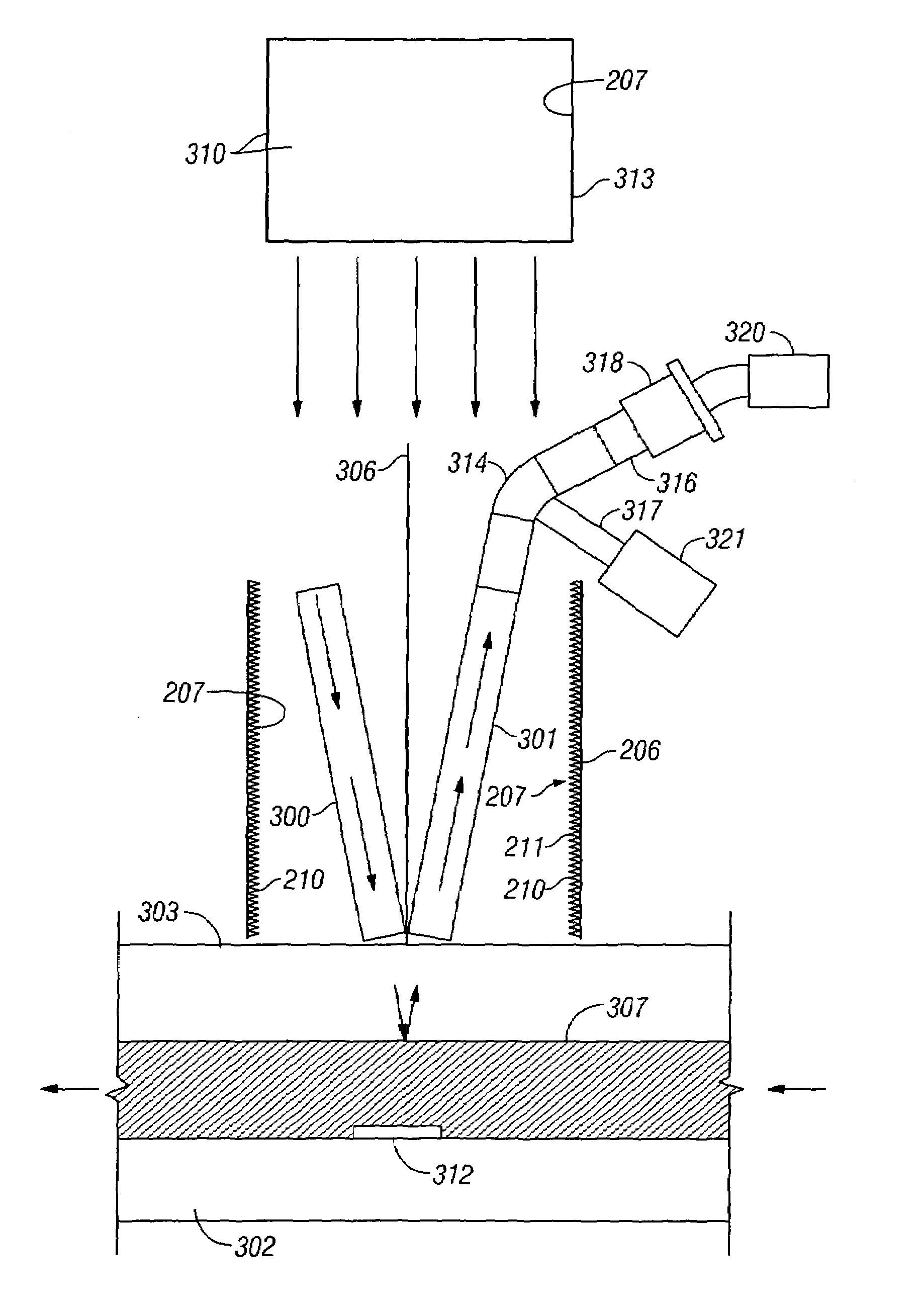
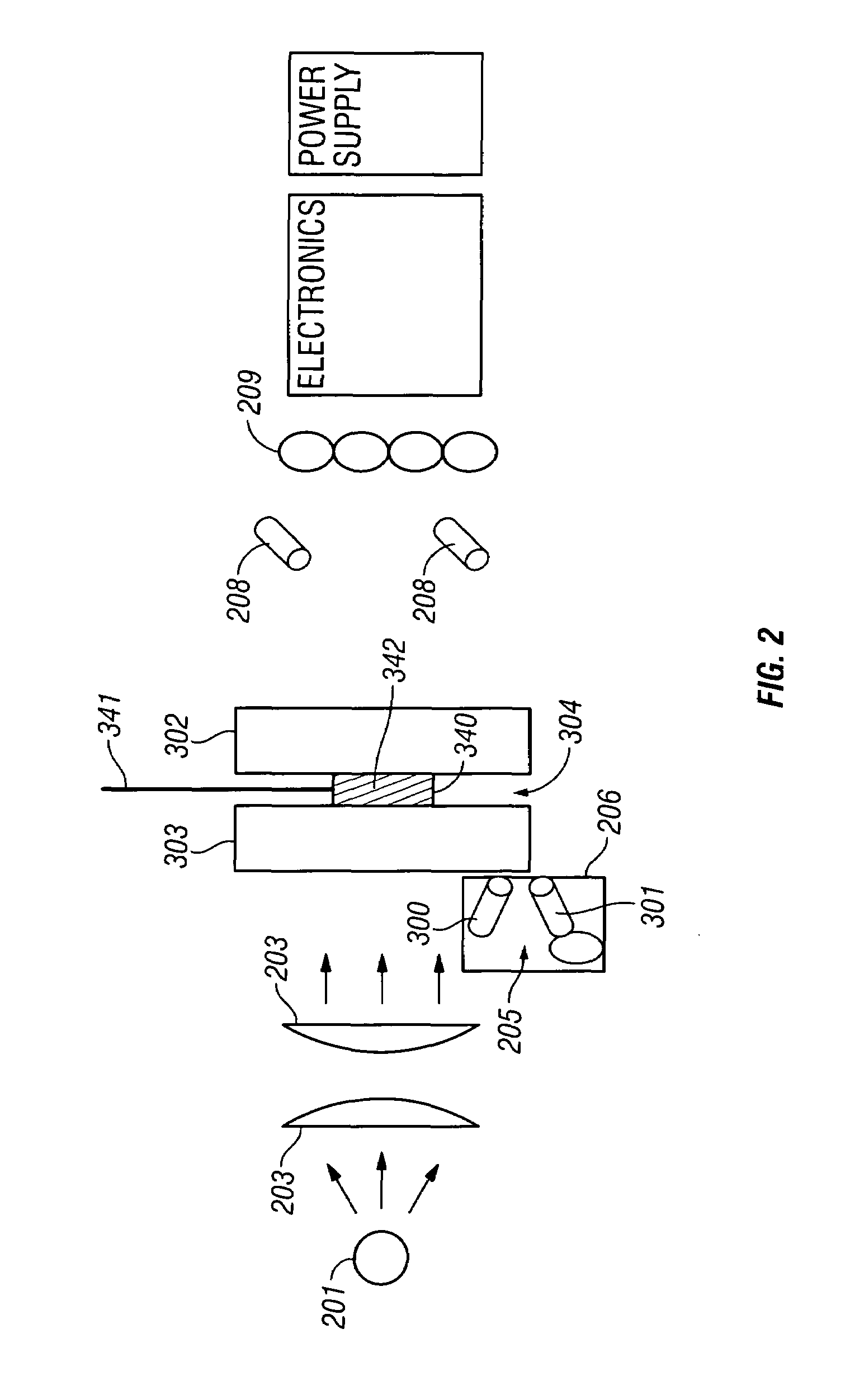
[0036]The present invention provides a method and apparatus for determining a number of formation fluid properties from a refractometer measurement. The present invention also provides a method and apparatus to more accurately distinguish between gas and liquid based on the much lower index of refraction of gas. The refractive index of a wellbore or formation fluid can be determined from the fraction of light, R, reflected off of the interface between the preferred transparent window, having a known refractive index and the formation fluid under analysis.

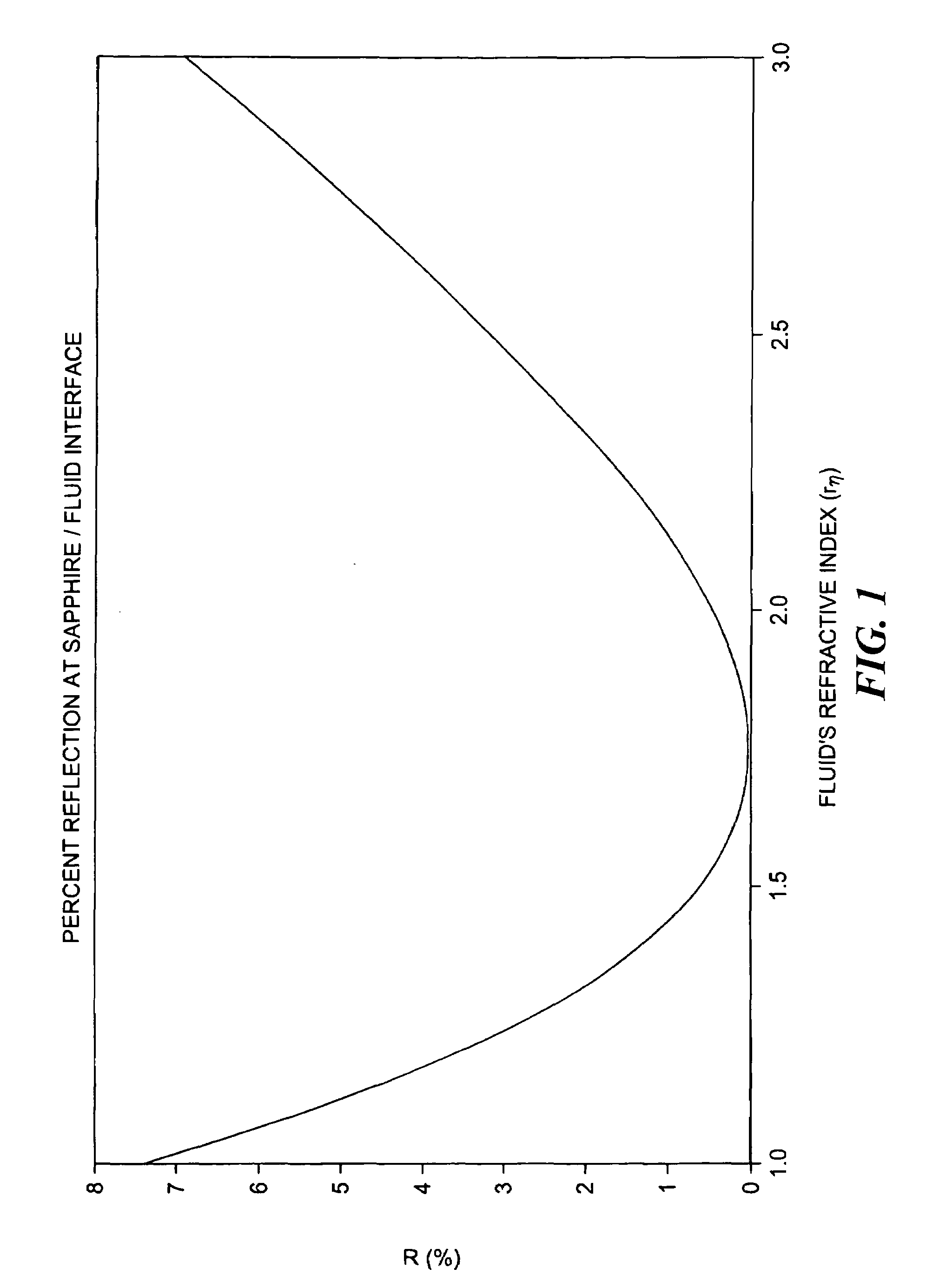
[0037]FIG. 1 shows the percentage of light reflected from the fluid / sapphire interface, when that light is incident perpendicular to the plane of the surface of the transparent window and interface. In this figure, the window has a fixed index of refraction of 1.75 but the index of refraction of the fluid varies. The minimum reflection occurs when the fluid's refractive index equals the window's refractive index, which for sapphire,...


PUM

PropertyMeasurementUnit
wavelengthaaaaaaaaaa
critical angleaaaaaaaaaa

Abstract

The invention relates to refractometry and attenuated reflectance spectrometry in a wellbore environment. Specifically, it pertains to a robust apparatus and method for measuring refractive index of fluids along a continuum (rather than in steps), and for measuring attenuated reflectance spectra, and for interpreting the measurements made with this apparatus to determine a variety of formation fluid parameters. The present invention provides a method and apparatus to distinguish between gas and liquid based on the much lower index of refraction of gas. It can also be used to monitor fluid sample clean up over time. The refractive index of a wellbore fluid is determined from the fraction, R, of light reflected off the interface between a transparent window that has a known refractive index and this fluid. Preferably, the refractive index is measured at some wavelength of light for which the fluid is not highly attenuating but is optimally attenuating. The adjacent transmission spectrometer can be used to correct the refractive index measurement for attenuation at those wavelengths, which it monitors. Also, this reflection-based refractometer design can be used as an attenuated reflectance spectrometer at highly attenuating wavelengths.

Description

CROSS REFERENCE TO RELATED APPLICATIONS[0001]This application is a continuation in part of and takes priority from U.S. patent application Ser. No. 10 / 119,492 filed on Apr. 10, 2002, now U.S. Pat. No. 6,683,681, by Rocco DiFoggio et al., entitled “A Method and Apparatus for Downhole Refractometer And Attenuated Reflectance Spectrometer” which is hereby incorporated herein by reference in its entirety.FIELD OF THE INVENTION[0002]The invention relates to refractometry and spectrometry in a wellbore environment. Specifically, it pertains to a robust apparatus and method for measuring refractive index of fluids along a continuum (rather than in steps), of measuring attenuated reflectance spectra, and to the interpretation of measurements made with this apparatus to determine a variety of formation fluid parameters. The refractometer and attenuated reflectance spectrometer disclosed here uses a simplified design, which is very appropriate for a downhole environment.BACKGROUND OF THE INVE...

Claims


Application Information

Patent Timeline
Patent Type & Authority Patents(United States)
IPC IPC(8): G01N21/41G01N21/35G01N1/00G01N21/43G01N21/55
CPCE21B47/102G01N21/41G01N21/3577G01N21/552G01N21/3504G01N21/43E21B47/113G01N27/226
Inventor DIFOGGIO, ROCCOWALKOW, ARNOLDBERGREN, PAULPEREZ, LOUIS
Owner BAKER HUGHES INC
Why Eureka
Try Eureka