Method for making multi-layer ceramic acoustic transducer

a multi-layer ceramic and transducer technology, applied in piezoelectric/electrostrictive transducers, generators/motors, mechanical vibration separation, etc., can solve the problems of reducing the electrical efficiency and element sensitivity, unable to optimize the parameters to match the electrical impedance of the cable, and difficulty in maintaining the tolerances necessary for ultrasound transducers

a multi-layer ceramic and transducer technology, applied in piezoelectric/electrostrictive transducers, generators/motors, mechanical vibration separation, etc., can solve the problems of reducing the electrical efficiency and element sensitivity, unable to optimize the parameters to match the electrical impedance of the cable, and difficulty in maintaining the tolerances necessary for ultrasound transducers

US7017245B2Inactive Publication Date: 2006-03-28GENERAL ELECTRIC CO

Image

  • Method for making multi-layer ceramic acoustic transducer
  • Method for making multi-layer ceramic acoustic transducer
  • Method for making multi-layer ceramic acoustic transducer

Examples


Embodiment Construction

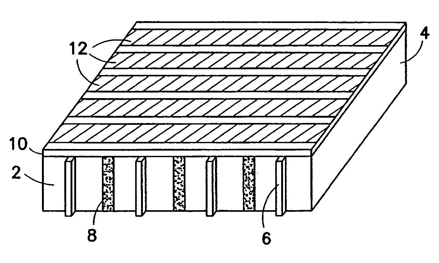
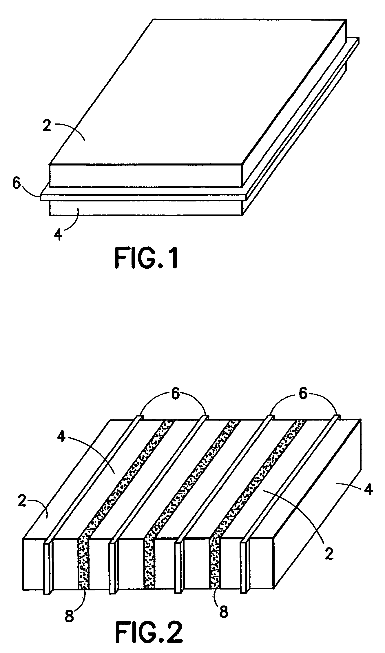
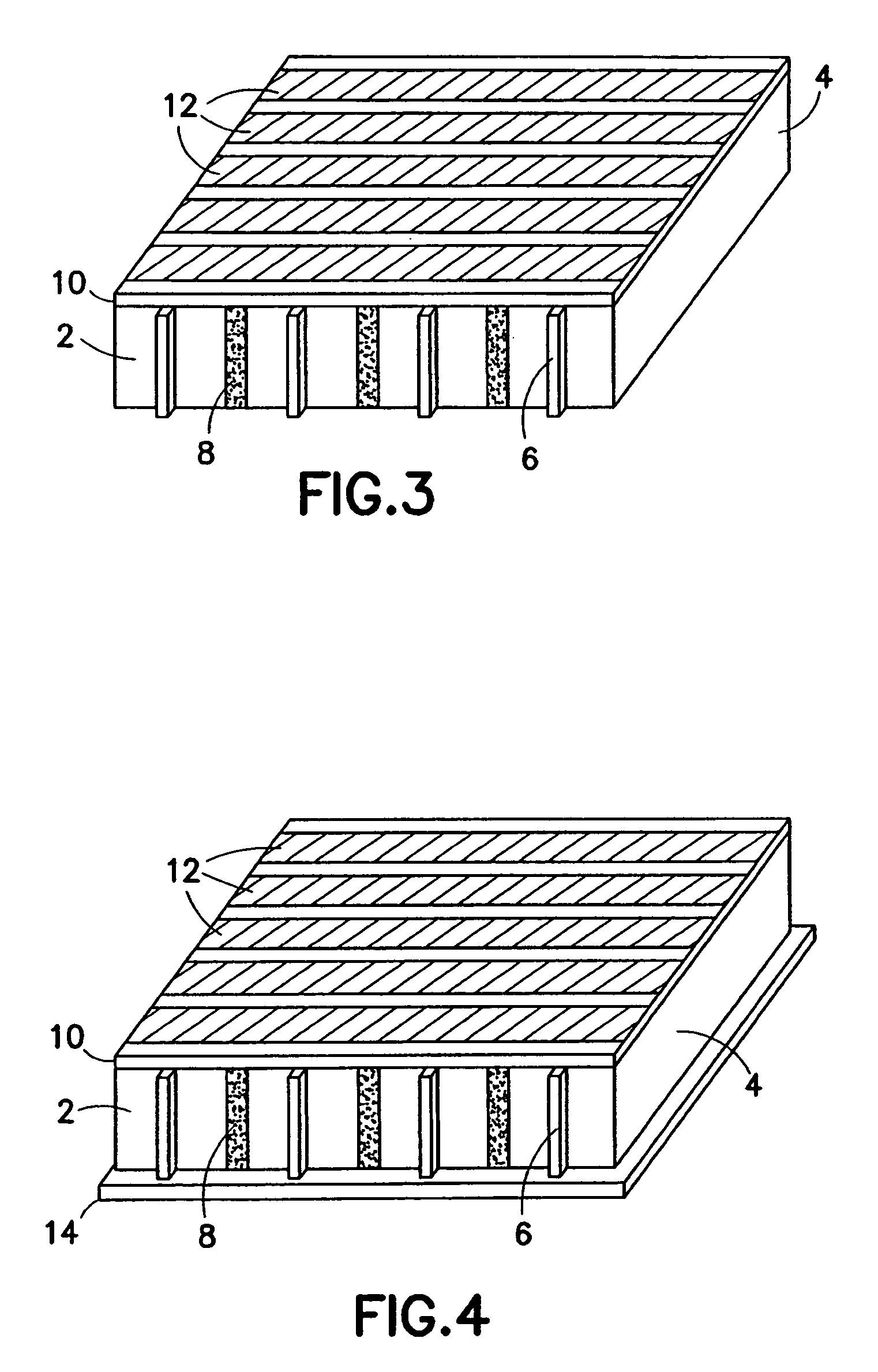
[0017]The invention is directed to a method for preparing a multi-layer ceramic acoustic stack comprised of an even number of ceramic layers. For the purpose of illustration, a method for preparing a two-layer ceramic acoustic stack will now be disclosed in detail. Two-layer stacks can themselves be stacked to construct multilayer stacks having four or more ceramic layers. The disclosed method is useful for preparing acoustic elements in both linear and multi-row acoustic arrays, as well as small elements for two-dimensional acoustic arrays. Such acoustic arrays are useful for medical imaging applications.

[0018]In accordance with the method for forming two-layer piezoelectric acoustic transducers disclosed in detail hereinafter, the structural integrity of the piezoelectric element is not weakened by removal of a portion of the element. The method is based on laminating two piezoelectric ceramic layers with confronting metallized surfaces. Optionally, a thin electrical conductor may...


PUM

PropertyMeasurementUnit
electrical impedanceaaaaaaaaaa

Abstract

A method for manufacturing a multi-layer acoustic transducer with reduced total electrical impedance. The method is based on the bonding of two piezoelectric ceramic layers with confronting metallized surfaces to a thin electrical conductor, then electrically connecting the top and bottom surfaces to form a wrap-around electrode while a center conductor forms a second electrode. The total electrical impedance of a two-layer ceramic stack comprised of piezoelectric layers connected in this manner is one-fourth that of a solid ceramic element of the same size. This provides for better matching of the acoustic stack impedance to that of the electrical cable, increased penetration depth for imaging within the body, and improved acoustic element sensitivity.

Description

BACKGROUND OF THE INVENTION[0001]This invention generally relates to multi-layer piezoelectric ceramic transducers. In particular, the invention relates to the design of ultrasound transducers to improve the sensitivity of an ultrasound imaging system.[0002]Acoustic transducers used in ultrasound imaging are constructed of a piezoelectric material whose surfaces are metal coated and connected to a potential (signal) and ground source respectively. This piezoelectric material is typically comprised of a composition of lead zirconate titanate (PZT) ceramic. During operation, a high-frequency electrical waveform is applied to the PZT electrodes, causing a change in ceramic dimension and generating an acoustic pressure wave or pulse. Conversely when an acoustic reflection contacts the surface of the piezoelectric material, it generates a voltage difference across the electrodes that is detected as a receive signal.[0003]Coaxial cables connecting the acoustic transducer to the system use...

Claims


Application Information

Patent Timeline
28 Mar 2006
Publication
US7017245B2
IPC
H01L41/083; H04R31/00; B06B1/06; H10N30/85; H03H9/13; H03H9/15; H04R17/00; H10N30/00; H10N30/01; H10N30/05; H10N30/50; H10N30/87
CPC
B06B1/0622; H01L41/313; Y10T29/49002; Y10T29/42; Y10T29/49007; H10N30/057; H10N30/063
Inventors
BAUMGARTNER, CHARLES E.; LEWANDOWSKI, ROBERT S.