Solder pastes for providing high elasticity, low rigidity solder joints

a technology of low rigidity and solder joints, applied in the direction of welding/cutting media/materials, solventing apparatus, manufacturing tools, etc., can solve the problems of new problem set, device and system failure, and the stress resulting from these mismatches do not disappear, and achieve low rigidity solder joints, high likelihood of mechanical deformation, and high elasticity

Active Publication Date: 2006-03-28
INDIUM CORP +1
View PDF26 Cites 22 Cited by
  • Summary
  • Abstract
  • Description
  • Claims
  • Application Information

AI Technical Summary

Benefits of technology

[0014]In another exemplary embodiment, a method of using a solder paste is disclosed resulting in a new solder interconnection with high elasticity and low rigidity when two parts being soldered together have a large mismatch in their coefficients of thermal expansion or have a high likelihood of mechanical deformity. The solder paste may be made by blending flux with a mixture of particles comprised of a dominant volume fraction of high melting temperature particles having solderable surfaces and a minor volume fraction of solder powder.
[0028]In accordance with other aspects of particular exemplary embodiments of the disclosure, the high melting temperature particles may be pretreated chemically so that their surfaces are protected by surface finishes which can preserve solderability, inhibit the reaction between particles and flux, and / or enhance the reliability of solder joints.
[0030]In accordance with additional aspects of particular exemplary embodiments of the present disclosure, the solder may also bond to pads of parts through solder wetting. The high porosity of the interconnection increases elasticity and reduces rigidity or modulus of a solder joint, thus allowing a high compliance for solder joints and hence a high tolerance against a mismatch in physical dimension between parts due to a large mismatch in their coefficients of thermal expansion or due to mechanical deformation during service life, and consequently grants a high fatigue resistance.

Problems solved by technology

The problems with the present state of the art are, for instance, problems that often arise due to significant mismatches in CTE.
If a solder joint is weak, the joint may rupture quickly and typically results in device and system failure.
However, in the case of a large mismatch in the CTE's or physical dimensions between parts, even a soft solder joint may be unable to cope and joint rupture typically results.
Contrarily, if a solder joint is very strong, a new problem set arises.
However, for devices with large mismatches in the CTE's or physical dimensions between parts, the stresses resulting from these mismatches do not disappear due to the use of strong rigid composite solder joints.
For instance, if a solder joint itself is too strong to fail, a device may fail at spots weaker than the joint, such as at the bonding between solder and pads, the bonding between solder and devices, or the body of a board / device itself, in order to relieve the stress.
The high melting temperature metal particles give the solder a larger standoff value for the substrate than normal solder powder allows, purportedly resulting in an increase in fatigue life.
However, the validity of this approach is compromised by the particle size allowed for in an associated dispensing or printing process.
Large high melting temperature metal particles do not allow adequate solder paste dispensing or printing.
On the other hand, small high melting temperature metal particles do not provide sufficient standoff, such that the solder joint is unable to cope with a large mismatch in the CTE's or physical dimensions between parts.
Although this rigid joint offers some advantage for typical electronic products, the rigidity could cause joint or component cracking particularly in the case of a large mismatch in the CTE's or physical dimensions between parts.
The '113 method is very labor intensive and requires the coating of metal particles with a second metal surface by plating, which is both time consuming and cost prohibitive.
When solder paste is deposited by printing or dispensing, and then reflowed between a substrate and an electrical component having a large mismatch in the CTE's or physical dimensions between parts, joint cracking or fatigue failure typically results either right after the soldering process or during service.

Method used


Image

  • Solder pastes for providing high elasticity, low rigidity solder joints
  • Solder pastes for providing high elasticity, low rigidity solder joints
  • Solder pastes for providing high elasticity, low rigidity solder joints

Examples


example 1

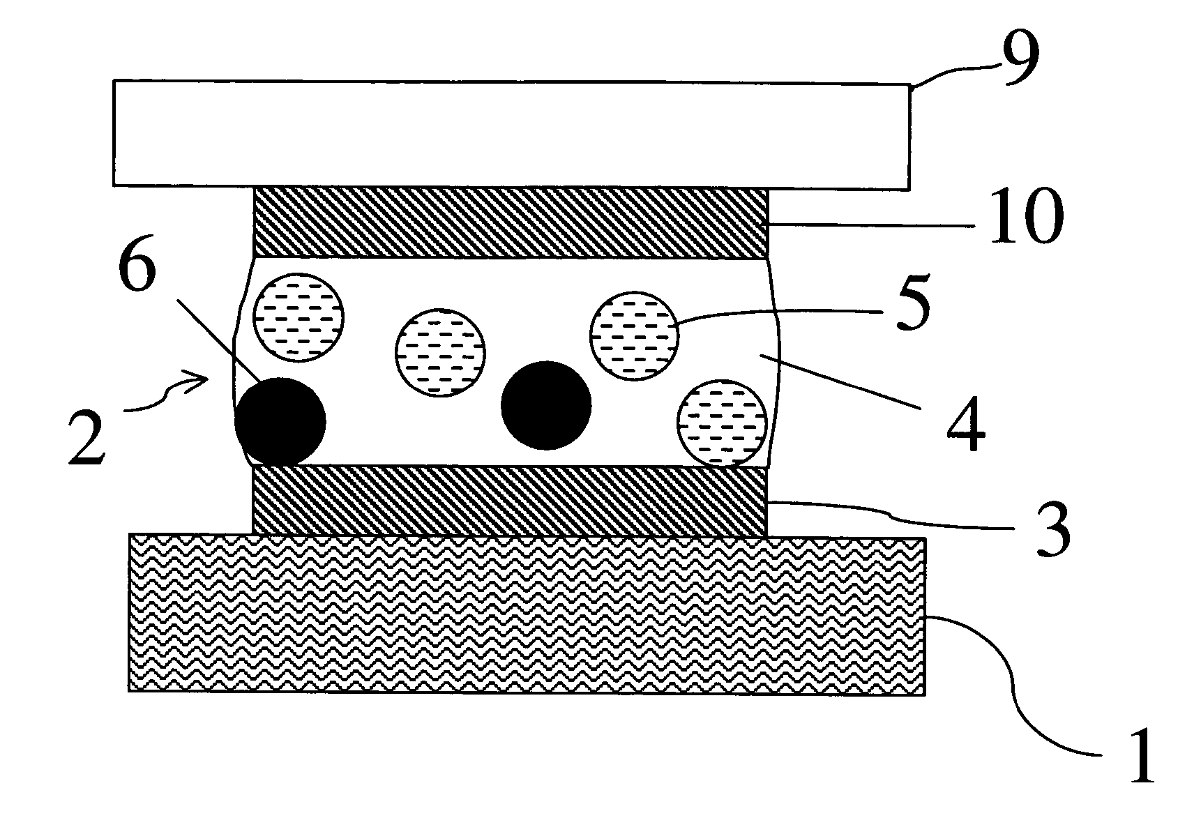
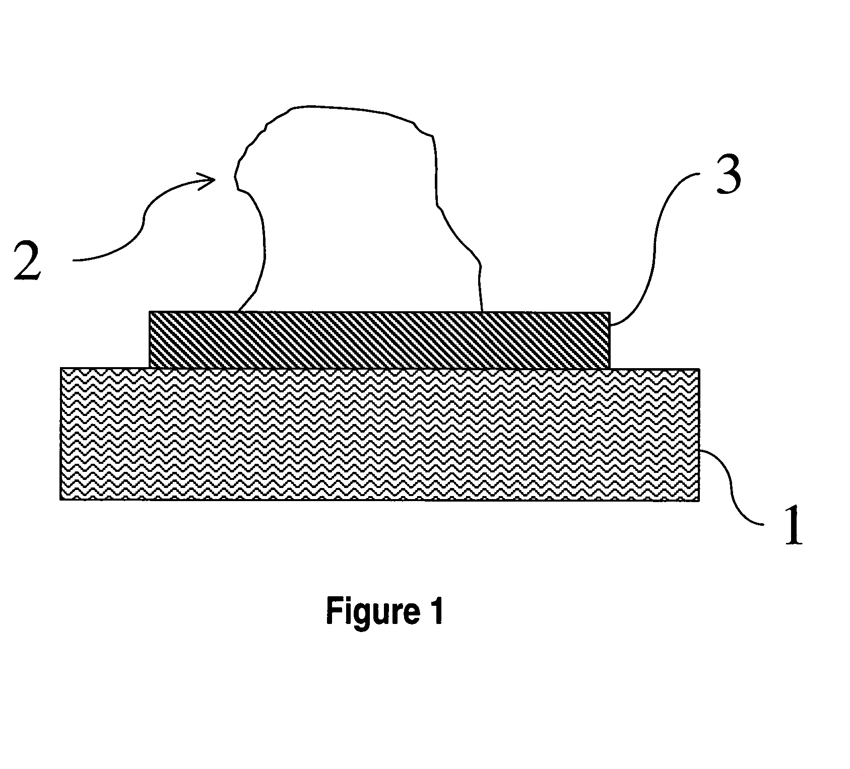
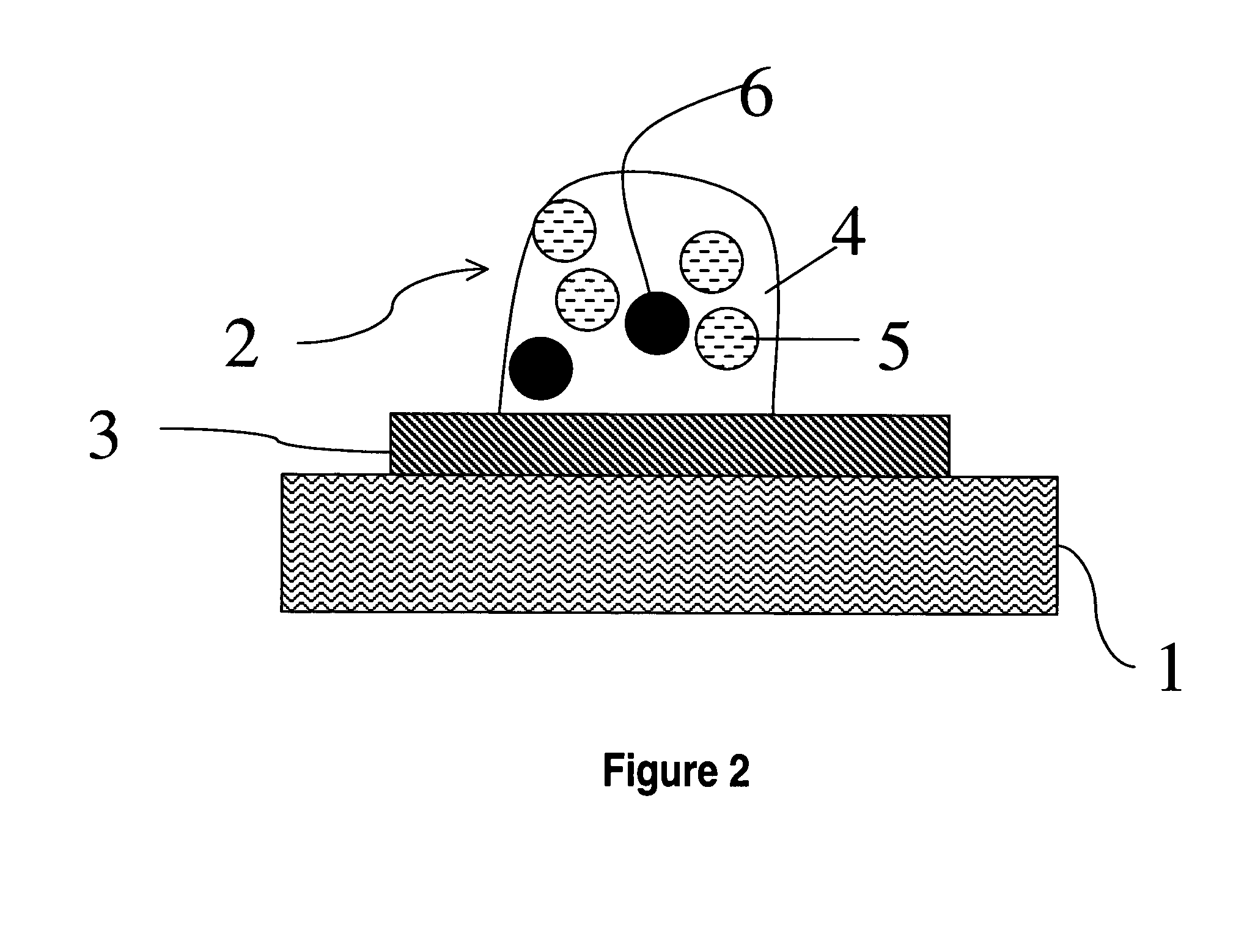
[0055]A joint between a ceramic coupon and an FR4 coupon may be made with a solder paste using 5.00 g of solder powder, 2.50 g of copper powder, and 2.13 g of flux. A cross section of the joint shows that there is approximately 2% porosity. The joint may be tested using an MTS lap shear tester. The load capacity of the joint is approximately 484 lbf / in2. The joint may be stretched approximately 9.3 mils. The joint is less porous than the joint shown in FIGS. 1–4.

example 2

[0056]A joint between a ceramic coupon and an FR4 coupon may be made with a solder paste using 5.00 g of solder powder, 5.00 g of copper powder, and 3.38 g of flux. A cross section of the joint shows that there is approximately 50% porosity. The joint may be tested using an MTS lap shear tester. The load capacity of the joint is approximately 325 lbf / in2. The joint may be stretched approximately 7.5 mils. The joint is similar in porosity to the joint shown in FIGS. 1–4.


PUM

PropertyMeasurementUnit
porosityaaaaaaaaaa
porosityaaaaaaaaaa
melting temperatureaaaaaaaaaa

Abstract

Solder pastes for providing high elasticity, low rigidity solder joints are disclosed. The solder pastes may be used between two parts having large mismatches in their coefficients of thermal expansion and / or when there is a high likelihood of mechanical deformity when the two parts are soldered together. In one particular exemplary embodiment, a solder paste may be realized as a composition comprising a solder powder and high melting temperature particles with a flux, wherein the ratio between solder powder and high melting temperature particles may be between 2:1 and 1:10.

Description

CROSS-REFERENCE TO RELATED APPLICATIONS[0001]This patent application claims priority to U.S. Provisional Application No. 60 / 516,274, filed Nov. 3, 2003, which is hereby incorporated by reference herein in its entirety.FIELD OF THE DISCLOSURE[0002]The present disclosure relates generally to compositions and methods of using the compositions for connection of materials, and, more particularly, to electronic and / or mechanical parts. The disclosure further provides for advanced interconnection solder pastes for electronic and / or mechanical parts, comprised of at least two different materials.BACKGROUND OF THE DISCLOSURE[0003]The present state of the art is that in many modern electronic devices, parts are bonded together by solder interconnections. The bonded parts are often composed of materials with significantly different coefficients of thermal expansion (CTE). For instance, a ceramic electronic device, with low CTE, may be soldered onto a polymeric printed circuit board with a high...

Claims


Application Information

Patent Timeline
Patent Type & Authority Patents(United States)
IPC IPC(8): B23K35/12B23K31/02B23K35/02B23K35/26B23K35/30B23K35/36H05K3/34
CPCB23K35/025H05K3/3484B23K35/0244B23K35/26H05K2201/0215B23K35/3612B23K2201/36B23K35/302B23K2101/36H05K3/3485
Inventor LIU, YANHERRON, DERRICKLEE, NING-CHENG
Owner INDIUM CORP
Why Eureka
Try Eureka