Device for removing carbon dioxide from exhaust gas

a carbon dioxide and exhaust gas technology, applied in steam, hydrogen sulfides, machines/engines, etc., can solve the problems of the withdrawal of the outlay on plant engineering for the liquid cycle of the absorbing liquid, and achieve the effect of reducing heat transfer and low thermal conductivity

Inactive Publication Date: 2006-04-04
GENERAL ELECTRIC TECH GMBH
View PDF25 Cites 57 Cited by
  • Summary
  • Abstract
  • Description
  • Claims
  • Application Information

AI Technical Summary

Benefits of technology

[0015]The absorber/desorber is preferably constructed in the manner of a coated regenerative heat exchanger and is equipped with a large reactive surface for the absorption and desorption of carbon dioxide, the core material which bears the coating

Problems solved by technology

A drawback of this method is that the device in which the carbon dioxide is released again must in each case be operated as an externall

Method used


Image

  • Device for removing carbon dioxide from exhaust gas
  • Device for removing carbon dioxide from exhaust gas
  • Device for removing carbon dioxide from exhaust gas

Examples


Embodiment Construction

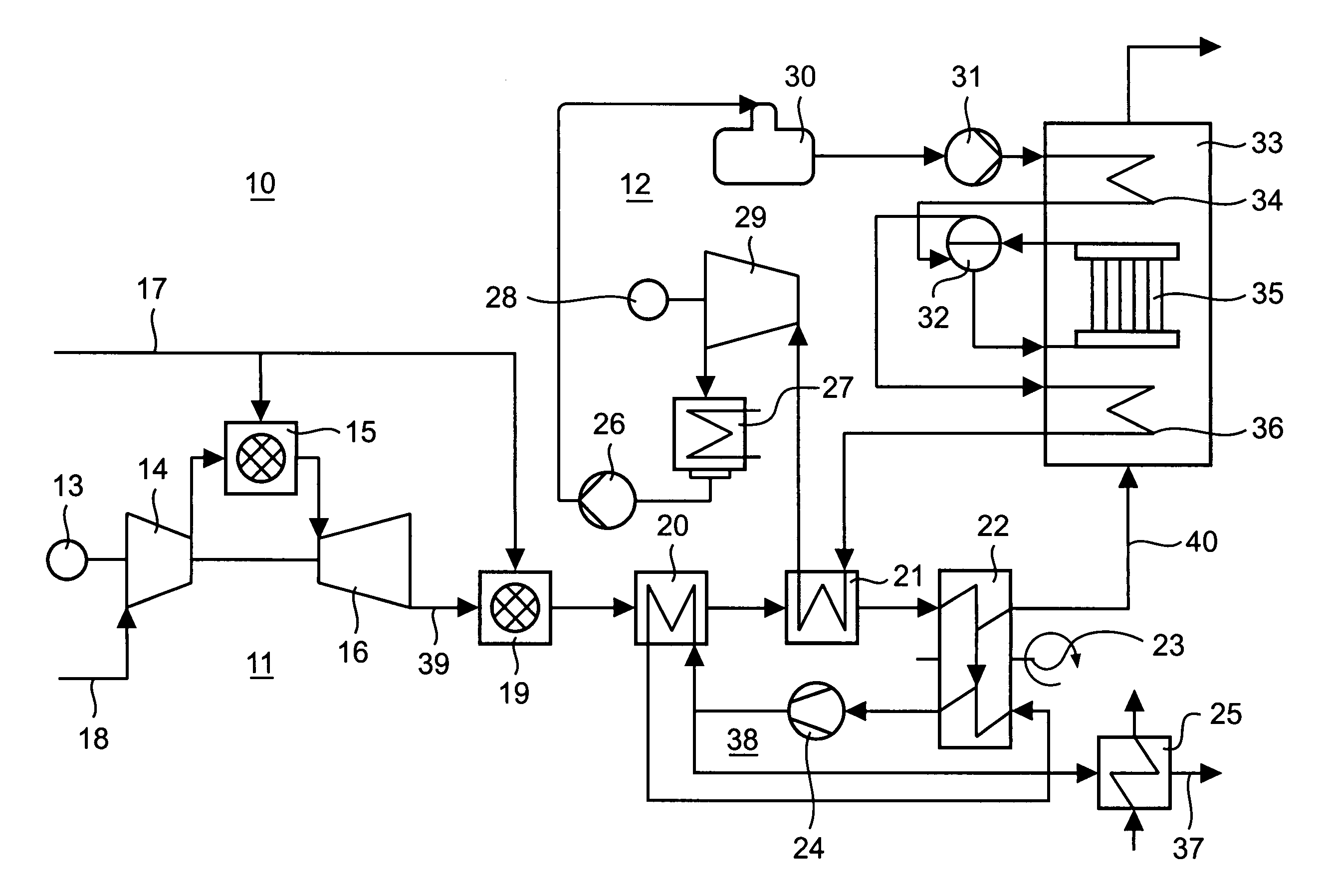
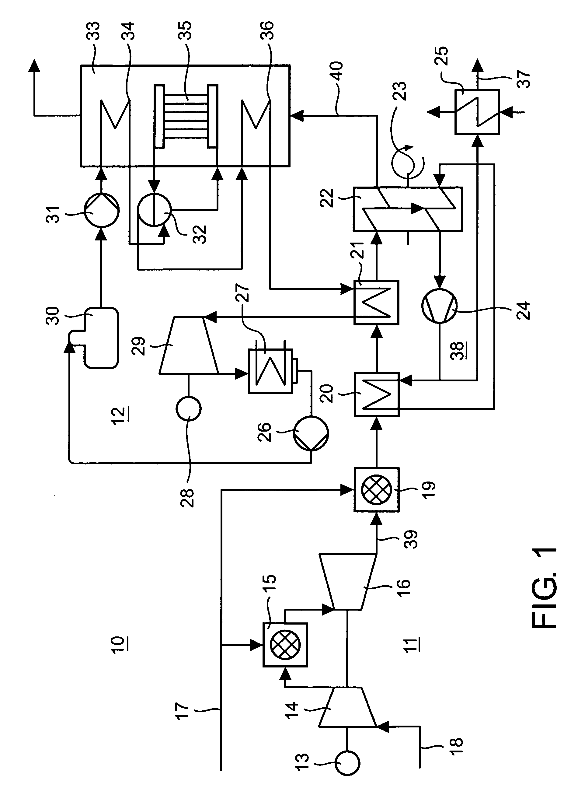
[0019]FIG. 1 illustrates the plant diagram of a combined cycle power plant 10 with a device for removing carbon dioxide from the exhaust gas. The combined cycle power plant 10 substantially comprises three plant parts, namely a gas turbine plant 11, a water / steam cycle 12 and a carbon dioxide cycle 38, all of which are coupled to one another.

[0020]The gas turbine plant 11 comprises a compressor 14, a first combustion chamber 15 and a gas turbine 16. Via an air inlet 18, the compressor sucks in combustion air and compresses it. The compressed air is used for combustion of a (liquid or gaseous) fuel in the first combustion chamber 15. The hot gas which is formed during the combustion is expanded in the gas turbine 16, which via a common rotor drives the compressor 14 and generates current via a connected first generator 13. The exhaust gas 39 from the gas turbine 15, after it has passed through a plurality of intermediate stages (19, 20, 21, 22), which will be dealt with in more detai...


PUM

PropertyMeasurementUnit
Thermal conductivityaaaaaaaaaa

Abstract

In a method for removing carbon dioxide from the exhaust gas from a gas turbine plant (11), which exhaust gas is subjected to a downstream heat recovery process (12, 33), preferably in the heat recovery steam generator (33) of a water/steam cycle (12), a simplification of the plant engineering is achieved by the fact that the carbon dioxide is removed from the exhaust gas (39) between the gas turbine plant (11) and the heat recovery process (12, 33), and that a rotating, regenerative absorber/desorber (22) is used to remove the carbon dioxide, the absorber side of which absorber/desorber is connected into the exhaust gas stream (39) and the desorber side of which absorber/desorber is connected into a carbon dioxide cycle (38).

Description

RELATED APPLICATION DATA[0001]This application is a divisional of application Ser. No. 09 / 820,680 filed on Mar. 30, 2001, now U.S. Pat. No. 6,596,248, and claims priority under 35 U.S.C. §§ 119 and / or 365 to German Application No. 100 16 079.4 filed on Mar. 31, 2000.[0002]The present invention relates to the fields of power plant engineering, which include the operation of a gas turbine, for example combined cycle power plants. It relates to a method and a device for removing carbon dioxide from the exhaust gas from a gas turbine plant which has a downstream heat recovery process.BACKGROUND OF THE INVENTION[0003]A method of this type and a device of this type are known, for example, from document U.S. Pat. No. 5,832,712.[0004]During the increasing discussion of possible climate changes caused by the increase of the carbon dioxide concentration in the Earth's atmosphere (“greenhouse effect”), which is attributable primarily to the burning of fossil fuels, such as natural gas, mineral...

Claims


Application Information

Patent Timeline
IPC IPC(8): F02C6/18B01D53/06B01D53/62F01K23/10F23J15/00F02C7/00F23L15/02
CPCB01D53/06F23J15/003F23J15/006B01D53/62Y02E20/326B01D2253/25B01D2257/504B01D2258/0283B01D2259/4009F23J2217/20F23J2217/50F23J2219/60F23J2219/70F23L2900/15042Y02C10/04Y02C10/06Y02C10/08Y02E20/16Y02A50/20Y02C20/40Y02E20/32
Inventor SCHIMKAT, ARMINBAUM, JUERGEN
Owner GENERAL ELECTRIC TECH GMBH
Why Eureka
Try Eureka