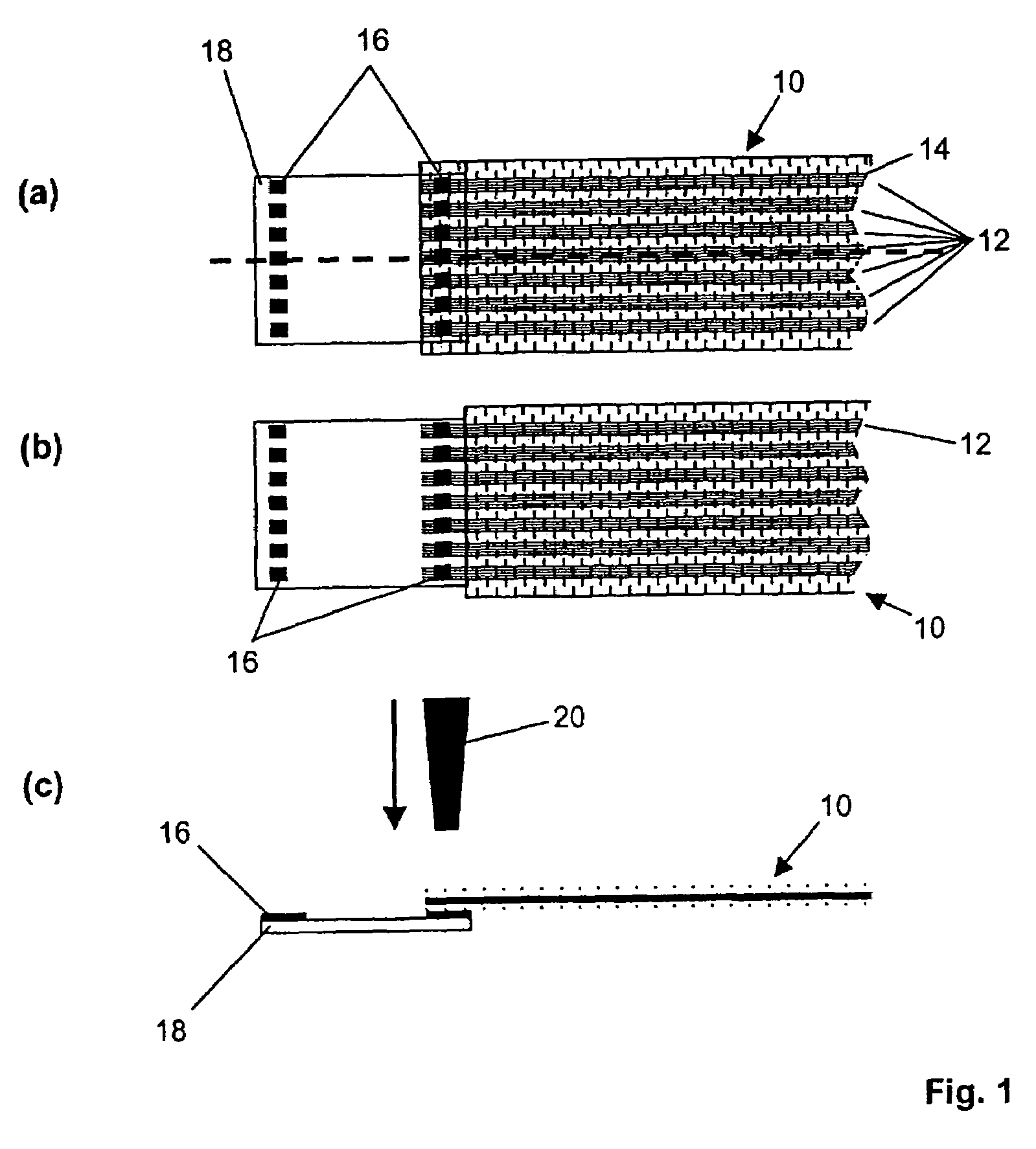
[0010]Preferably, the textile material is a fabric and the conductor comprises at least one weft and / or warp thread of the fabric. In this case, a fabric is understood to be a textile areal structure comprising two thread systems which cross one another in particular at right angles and are referred to—as usual—as warp and weft. The warp lies in the longitudinal direction of the weaving process, while the weft direction runs transversely with respect to the weaving direction. The conductor may be synthetic threads with conductive fine
metal wires spun therein. As an alternative, the conductor may also comprise a
thin metal wire, for example a fine silver or
copper wire, which forms a weft or warp thread of the fabric. Preferably, the conductor does not comprise a single weft or warp thread, but rather a multiplicity of weft or warp threads arranged adjacent, in particular, in the fabric. An electrical interruption of a fine
metal wire in one of the threads does not then lead to an interruption of the electrical
conductivity of the conductor, thus resulting in a redundant arrangement having higher reliability. In order to ensure a better
electrical connection of the conductor to the contact point, it may be advantageous to remove weft or warp threads which adjoin the conductor in the region of the conduct-making zone prior to the
electrical connection of the conductor to the contact point.
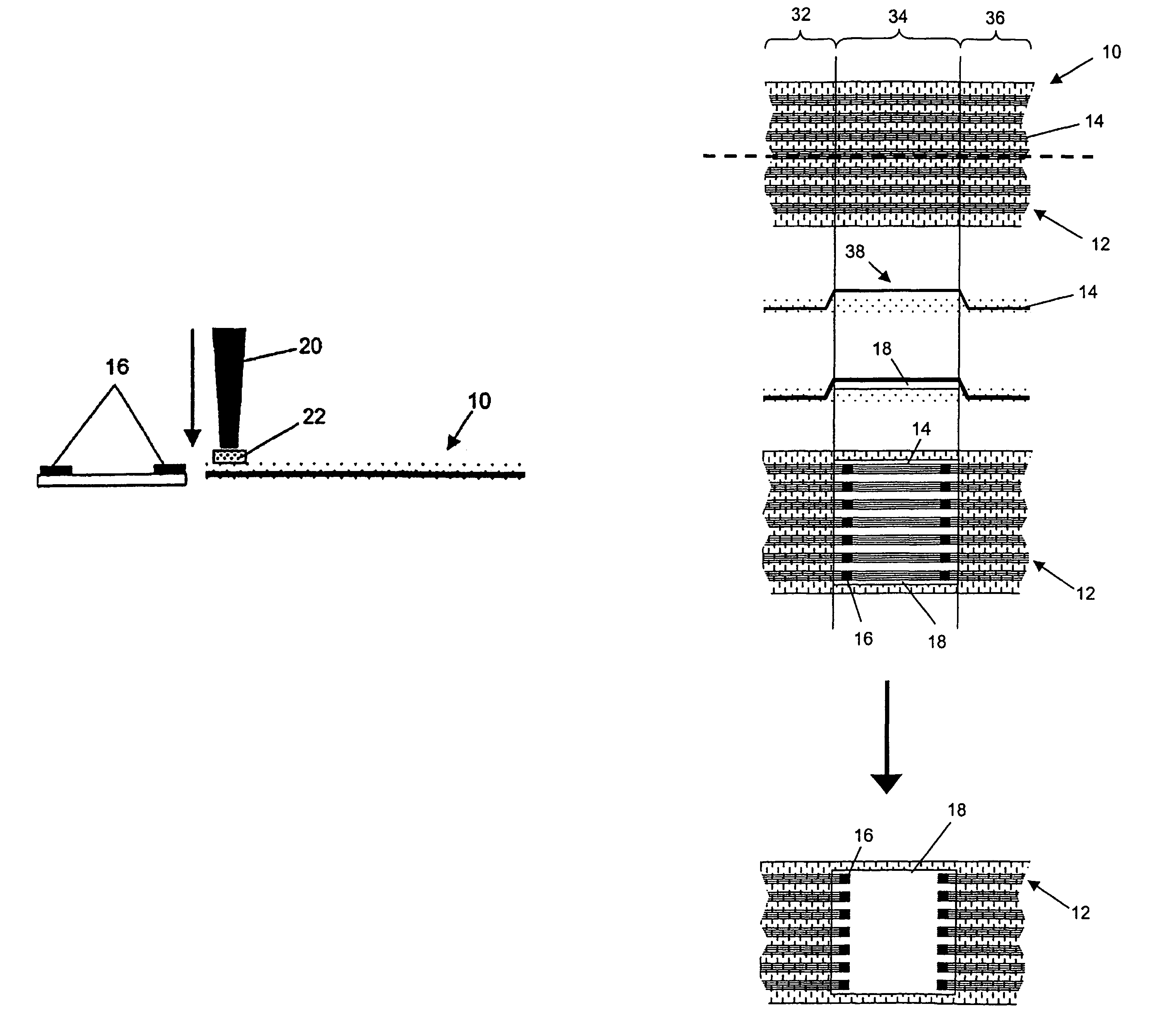
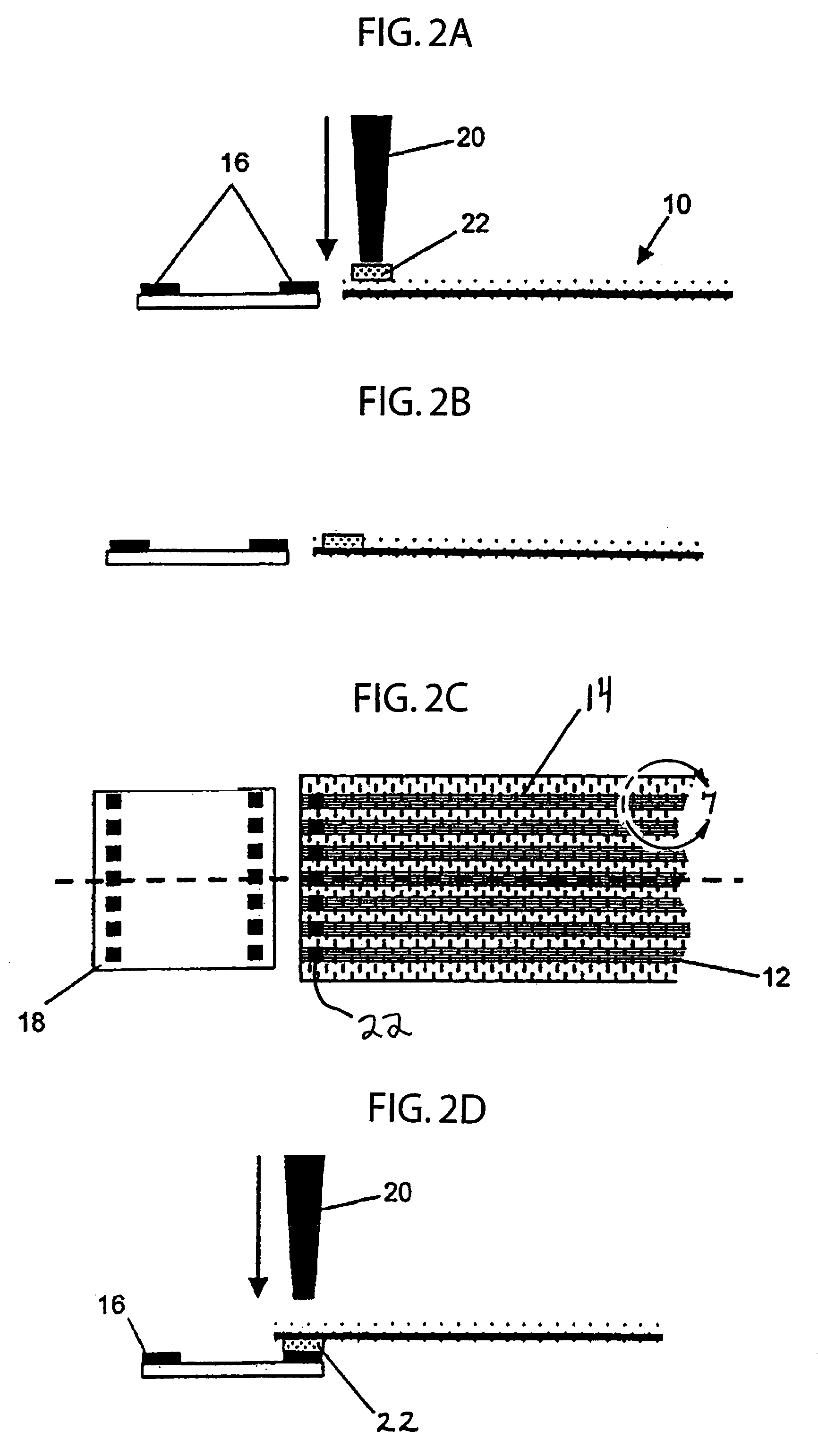
[0013]Preferably, the step of electrical connection of the conductor to the contact point comprises the application of a solder agent to at least one region of the contact point and the mechanical pressing of the conductor onto the contact point provided with solder agent. It has surprisingly been ascertained that simply heating the contact point which is provided with solder agent and at which the conductor that is to be electrically connected is arranged leads to satisfactory electrical connection results only to a limited extent. However, the electrical connection can be considerably improved by virtue of the fact that the step of electrical connection of the conductor to the contact point comprises the step of mechanical pressing of the conductor onto the contact point provided with solder agent. By way of example, if the conductor comprises synthetic fibers with an electrically insulated metal wire spun in, then the improvement in the electrical connection properties that is attributable to the mechanical pressing-on is attributable through a process of mechanical displacement of the thermally decomposed insulating sheath, which process enables the solder agent to come into contact with a larger surface of the metal wire. In comparison with connection methods in which only the solder agent is melted in a “static” state, such a “dynamic” mechanical pressing-on method achieves better electrical connection results.
[0015]As an alternative, it may be provided that the contact point is coated at least in regions with a conductive
adhesive preferably having
chemical constituents that destroy a possible insulating sheath of the at least one fine metal wire of the conductor. In this case, too, the mechanical pressing-on step improves the electrical contact between conductor and contact point.
[0029]The electronic component is preferably a flexible strip, i.e. a flexible
printed circuit board which comprises for example
polyethylene (PE) with conductor tracks (for example
copper tracks) applied thereto. Such a flexible strip advantageously permits
adaptation of the distances between the electrical connecting points between the electronic component and the textile material, so that the flexible strip functions as an “adapter piece”. Particular advantages arise if the textile material chosen is a
synthetic fiber fabric which is coordinated with the material of the flexible strip in such a way that a seamless and stable transition is achieved by fusion or
adhesive bonding or similar connection techniques.
[0036]Preferably, the method comprises the further steps of positioning of an insulating film onto that side of the textile material which is opposite to the component for the insulation of the contact point, and fixing of the insulating film onto the textile material. This produces a “sandwich-like” construction in which the textile material is arranged between the component and the insulating film. The insulating film increases the
mechanical stability of the construction and provides for a reliable electrical insulation of the electrically connected conductors. As an alternative to the insulating film used, which may be a thin
plastic film, the contact point may be electrically insulated by application of an insulating
coating or an impregnation.

