Power circuit for battery
a power circuit and battery technology, applied in the direction of engine starters, electric generator control, instruments, etc., can solve the problems of inability to carry out predetermined start-up operation of the motor of a vehicle, and inability to supply a sufficient electric power to a motor, so as to prevent the reduction of electric power and increase the charge of electric power
- Summary
- Abstract
- Description
- Claims
- Application Information
AI Technical Summary
Benefits of technology
Problems solved by technology
Method used
Image
Examples
embodiment 1
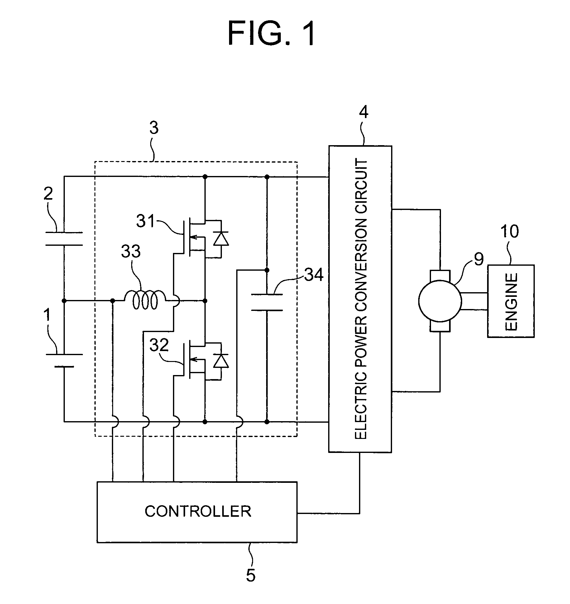
[0037]FIG. 1 is a circuit diagram showing a configuration of a power circuit for a battery according to Embodiment 1 of the present invention. As shown in the figure, a battery (first battery group) 1 and a capacitor group 2 as a second battery group are connected in series with each other to constitute a series-connected power supply. The capacitor group is constituted by capacitors each having a large capacity. For example, an electrical double layer capacitor, an aluminum electrolytic capacitor or the like can be used in the capacitor group. While not illustrated in FIG. 1, an electrical load (not shown; refer to Patent Document 1) such as an on-vehicle apparatus is connected to the battery 1. Here, in the following description, it is supposed that the battery 1 is an energy storage source, disposed on a low voltage side, of the above-mentioned series-connected power supply, and the capacitor group 2 is an energy storage source, disposed on a high voltage side, of the above-menti...
embodiment 2
[0062]FIG. 9 is a flow chart showing a flow of an operation of a power circuit for a battery according to Embodiment 2 of the present invention. Note that since a configuration of the power circuit for a battery according to Embodiment 2 of the present invention is the same as that of Embodiment 1 shown in FIG. 1, the reference should be made to FIG. 1 in this regard, and a detailed description is omitted here.
[0063]As shown in FIG. 9, in Embodiment 2, first of all, when an engine start-up command is issued in Step S10, in Step S11, it is judged whether or not the voltage across the terminals of the battery 1 is higher than a second threshold voltage VTH2 (e.g., 8.0 V). If it is judged in Step S11 that the voltage across the terminals of the battery 1 is higher than the second threshold voltage VTH2, then the operation proceeds to Step S12. The maximum efficiency control described in Embodiment 1 is carried out, and in Step S15, the engine is started. At this time, a judgment on the...
embodiment 3
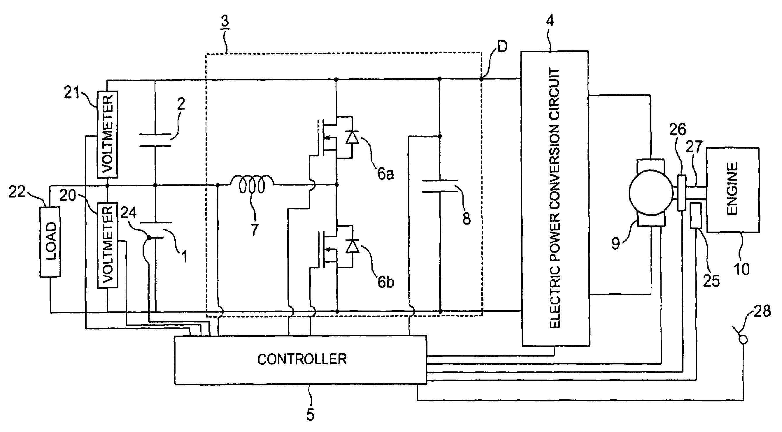
[0080]FIG. 11 is a circuit diagram showing a configuration of a power circuit for a battery according to Embodiment 3 of the present invention. FIG. 12 is a detailed block diagram of a controller shown in FIG. 11. FIGS. 13 and 14 are a flow chart of regenerative control in FIG. 11. FIG. 15 is a diagram showing how charging is carried out in a power circuit for a battery shown in FIG. 11.
[0081]As shown in FIG. 11, the power circuit for a battery includes: a battery 1 as a first energy storage source; a capacitor 2 which is connected in series with the battery 1 and which serves as a second energy storage source having an allowable input current larger than that of the battery 1; a DC / DC converter 3 inserted between the battery 1 and the capacitor 2; an electric power conversion circuit 4 connected between terminals of a series-connected body of the battery 1 and the capacitor 2; and a controller 5 for controlling the DC / DC converter 3 and the electric power conversion circuit 4.
[0082...
PUM
 Abstract
Description
Claims
Application Information
 - R&D
- Intellectual Property
- Life Sciences
- Materials
- Tech Scout
- Unparalleled Data Quality
- Higher Quality Content
- 60% Fewer Hallucinations
Browse by: Latest US Patents, China's latest patents, Technical Efficacy Thesaurus, Application Domain, Technology Topic, Popular Technical Reports.
© 2025 PatSnap. All rights reserved.Legal|Privacy policy|Modern Slavery Act Transparency Statement|Sitemap|About US| Contact US: help@patsnap.com


