
Hologram recording and reproducing apparatus

a technology of optical information and reproducing apparatus, which is applied in the field of optical information recording and reproducing apparatus, can solve the problems of difficult realization of phase conjugation mirrors and system size reduction, and achieve the effect of high density

Inactive Publication Date: 2006-04-04
PIONEER CORP
View PDF7 Cites 11 Cited by
  • Summary
  • Abstract
  • Description
  • Claims
  • Application Information

AI Technical Summary

Benefits of technology

[0011]It is therefore an object of the present invention to provide a hologram recording and reproducing apparatus which is capable of recording a hologram in a holographic memory at a high density and capable of being miniaturized.

Problems solved by technology

Accordingly, there is a problem with the disadvantage for system size reduction.
However, it is not easy to realize such a phase conjugation mirror.

Method used


Image

  • Hologram recording and reproducing apparatus
  • Hologram recording and reproducing apparatus
  • Hologram recording and reproducing apparatus

Examples


Embodiment Construction

[0030]Preferred embodiments according to the present invention will be described with reference to the accompanying drawings hereinafter.

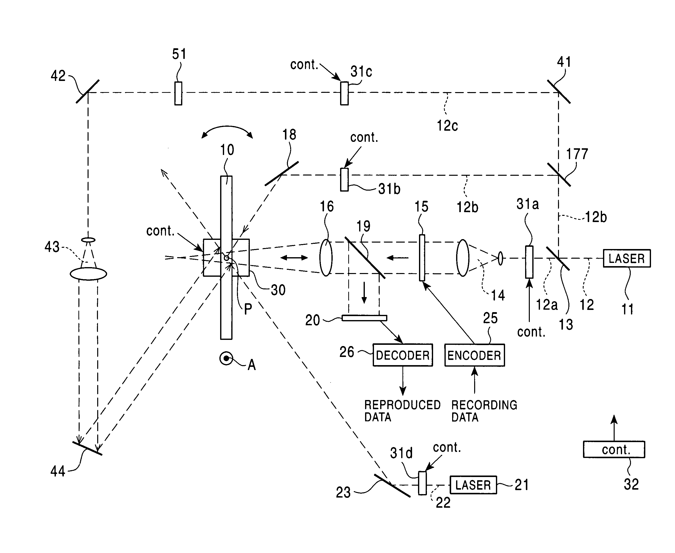
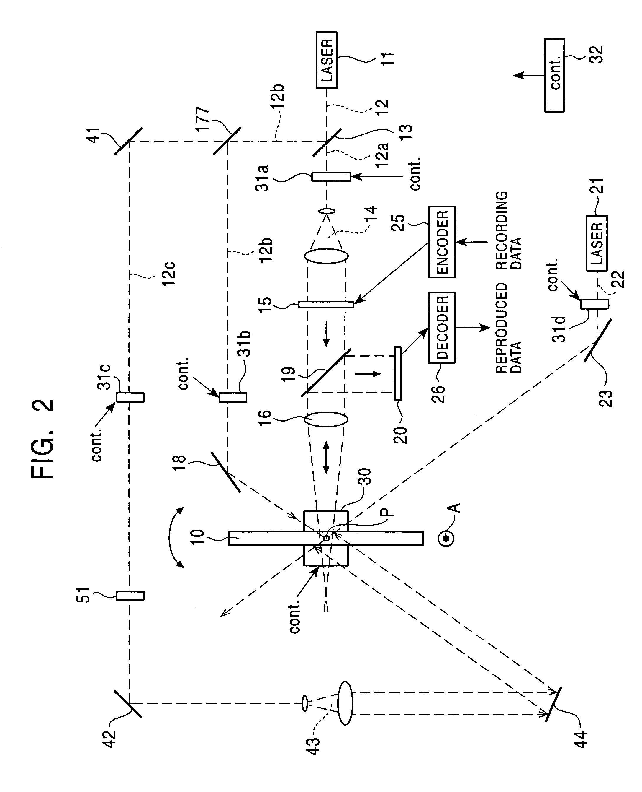
[0031]As shown in FIG. 2, a light source 11 of e.g. a wavelength of 532 nm for generation of signal light and reference light is a combination of a YAG laser and a SHG device. A laser light beam 12 emitted from the light source 11 is split into a signal light beam 12a and a recording reference light beam 12b by a beam splitter 13. The signal light beam 12a and the recording reference light beam 12b are guided and irradiated to the same position P in a recording medium 10 by way of different optical paths, respectively.

[0032]On the optical path of the signal light beam 12a, arranged are a shutter 31a, a beam expander 14, an SLM 15, a beam splitter 19 and a Fourier transforming lens 16. The shutters 31a, 31b and 31c are provided to open and close the optical paths of light beams 12a, 12b and 12c, respectively. These shutters are driven to open and cl...


PUM

PropertyMeasurementUnit
wavelengthaaaaaaaaaa
angleaaaaaaaaaa
wavelength rangeaaaaaaaaaa

Abstract

A hologram recording and reproducing apparatus preforms to record data on a recording medium and reproduce data from the recording medium. The recording medium is made of a photorefractive crystal having a parallel plate shape. The apparatus includes: a support portion for detachably supporting and rotating the recording medium; a recording-reference-light-beam-supplying-portion for supplying a coherent recording reference light beam propagating along an optical axis to a major surface of the recording medium; a signal-light-beam-supplying-portion for supplying a coherent signal light beam which is modulated in accordance with image data, in an optical path into the recording medium such that the signal light beam intersects with the reference light beam to produce an optical interference pattern with the reference and signal light beams within the recording medium; a reproducing-reference-light-beam-supplying-portion for supplying into the recording medium a coherent reproducing reference light beam propagating in an opposite direction along the optical axis of the recording reference light beam to generate a phase conjugation wave from a refractive-index grating of the light interference pattern; a splitting portion for splitting the phase conjugation wave from the optical path of the signal light beam to image a dot pattern with the phase conjugation wave; a photo-detecting portion for detecting the dot pattern imaged with the phase conjugation wave to reproduce the image data.

Description

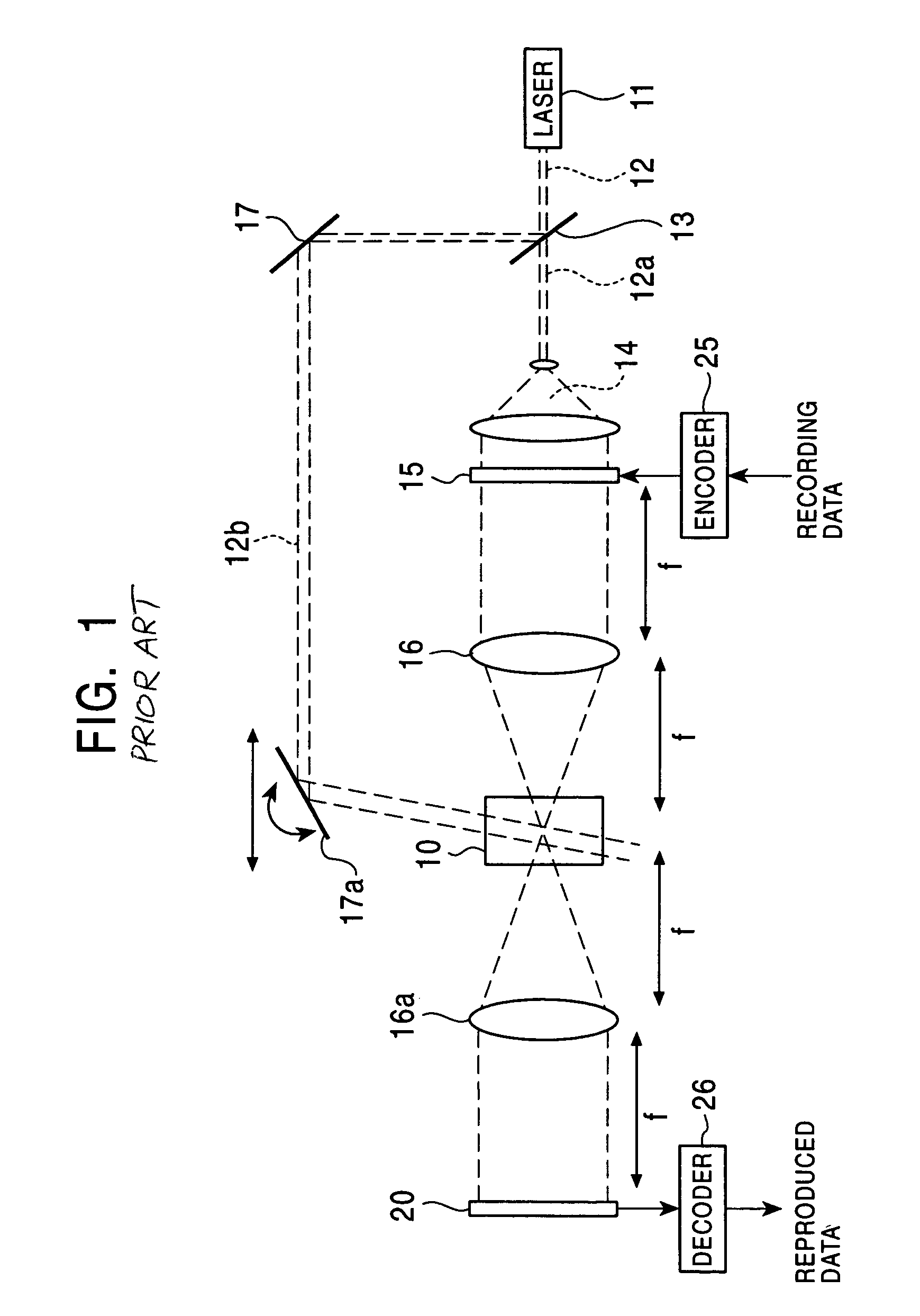
BACKGROUND OF THE INVENTION[0001]1. Field of the Invention[0002]The present invention relates to an optical information recording and reproducing apparatus utilizing a recording medium formed of a photorefractive material, i.e. so-called a holographic memory.[0003]2. Description of the Related Art[0004]A holographic memory system is known as a digital information recording system which applies the principle of holography. The information recording system is characterized by recording information signals recorded on a recording medium as optical signals. For the recording medium, a photorefractive crystal such as lithium niobate single crystals are used.[0005]There is a conventional holographic recording and reproducing method utilizing the Fourier transform.[0006]FIG. 1 shows a conventional 4f-based holographic recording and reproducing apparatus. A laser light beam 12 emitted from a laser light source 11 is split into a signal light beam 12a and a reference light beam 12b in a beam...

Claims


Application Information

Patent Timeline
Patent Type & Authority Patents(United States)
IPC IPC(8): G11B7/00G03H1/26G03H1/04G03H1/16G03H1/22G11B7/0065G11B7/125G11B7/1275G11B7/128G11B7/135G11B7/1395
CPCG11B7/1395G03H1/22G03H1/2286G11B7/0065G11B7/00772G11B7/083G11B7/1275G11B7/128G03H1/16G03H1/265G03H2001/026G03H2001/0268G03H2222/31G03H2222/56G03H1/181
Inventor ITOH, YOSHIHISAMATSUSHITA, HAJIME
Owner PIONEER CORP
Learn More