
Adjustable antenna feed network with integrated phase shifter

Inactive Publication Date: 2006-04-11
COMMSCOPE TECH LLC
View PDF30 Cites 10 Cited by
  • Summary
  • Abstract
  • Description
  • Claims
  • Application Information

AI Technical Summary

Benefits of technology

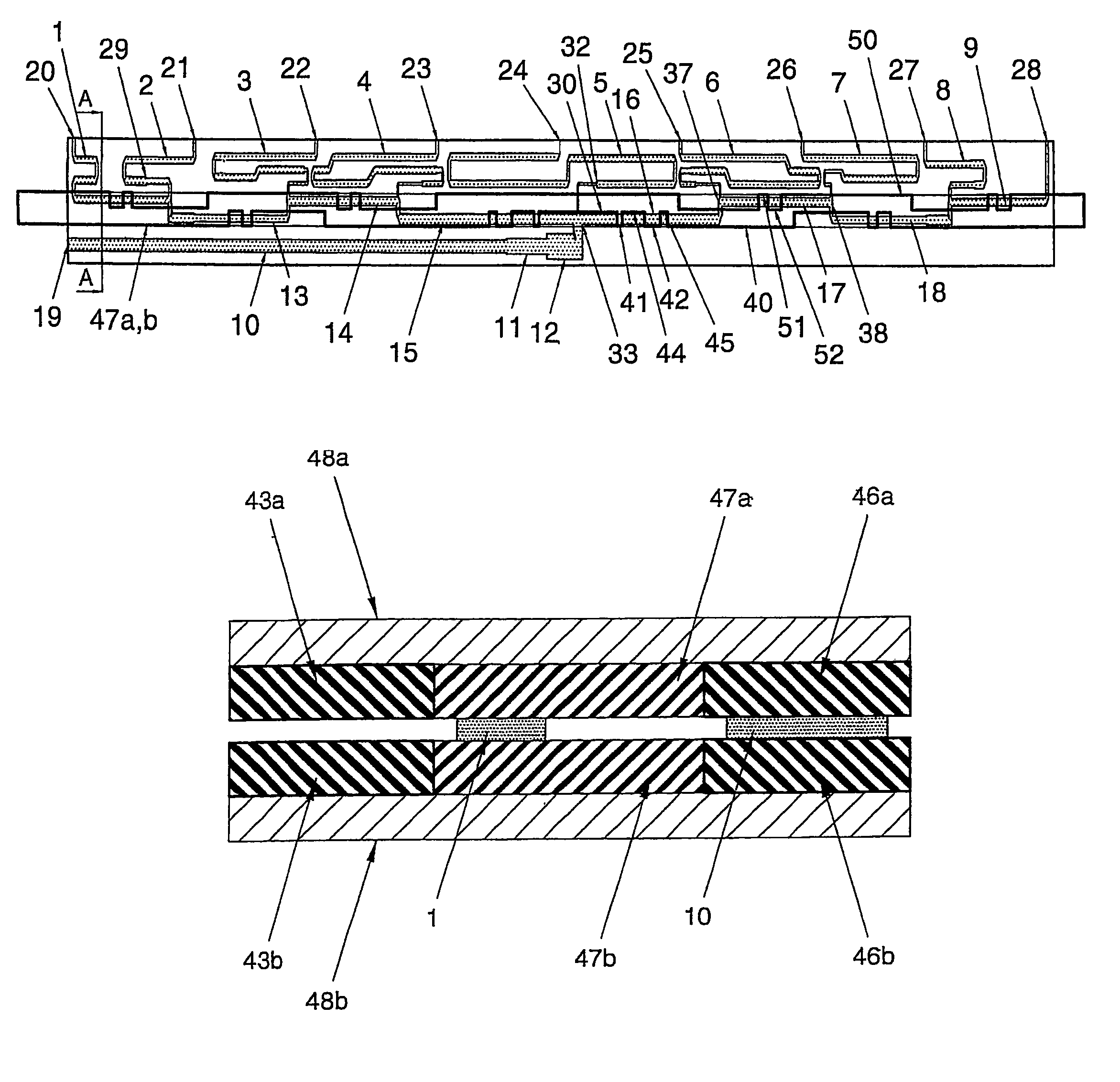
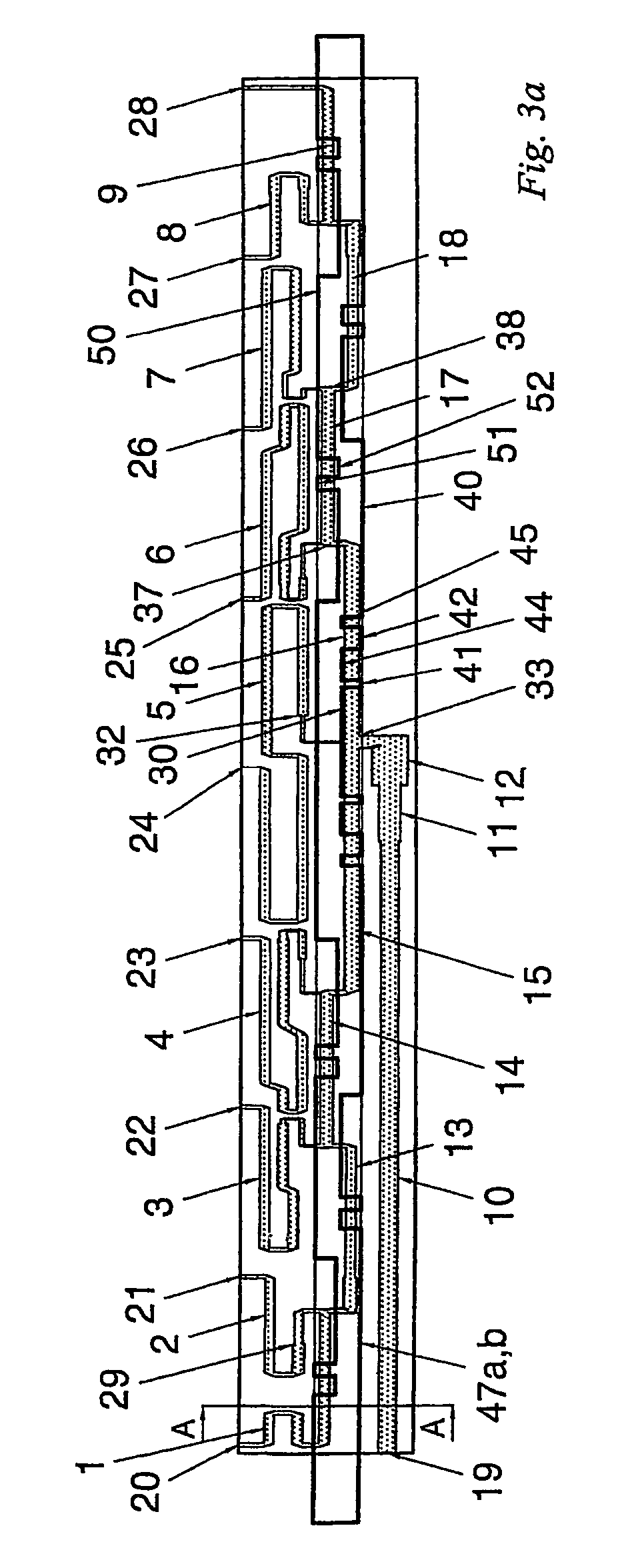
[0013]A first aspect of the invention provides a device for feeding signals between a common line and two or more ports, the device including a branched network of feedlines coupling the common line with the ports, at least one of the feedlines having a transformer portion of varying width for reducing reflection of signals passing through the network; and a dielectric member mounted adjacent to the network which can be moved along the length of at least one of the feedlines to synchronously adjust the phase relationship between the common line and one or more of the ports, the dielectric member having one or more transformer portions for reducing reflection of signals passing through the network.
[0014]The first aspect of the invention provides a means for integrating two types of transformer into the same device. As a result the wave impedance at the common line can be better matched to the wave impedance at the ports, whilst maintaining a relatively compact design.
[0021]Typically the dielectric member is formed with a transformer portion for reducing reflection of signals passing the leading or trailing edge of the space or region of reduced permittivity. In contrast to the arrangement of FIG. 1, the wave impedance at the transformer portion can decrease in the direction of the ports.
[0024]The fourth aspect of the invention relates to a preferred form of transformer, which is easier to fabricate than the transformer of FIG. 2. The transformer is also easier to tune according to the requirements of the feed network (by selecting the position and size of the second space or region).
[0034]The sixth aspect of the invention provides a preferred method of manufacturing a dielectric member, which can be utilised in the device of the second, third or fourth aspects of the invention, or any other device in which such a design is useful. The space may be left free, or may be subsequently filled with a solid material having a different (typically lower) permittivity to the removed material. This provides a more rigid structure.
[0042]A tenth aspect of the invention provides a device for feeding signals between a common line and two or more ports. The device includes a branched network of feedlines coupling the common line with the ports via one or more junctions, the one or more junctions include a main junction, which includes the common line. Also included is a dielectric member mounted adjacent to the network having a region of relatively high permittivity and one or more transformer portions for reducing reflection of signals passing through the network. The dielectric member can be moved along the length of at least one of the feedlines to synchronously adjust the phase relationship between the common line and one or more of the ports. The dielectric member is formed with a second region having a space or region of relatively low permittivity, the second region overlapping the main junction.

Problems solved by technology

In high performance antennas these components strongly interact with each other, sometimes making a desirable beam shape unrealisable.
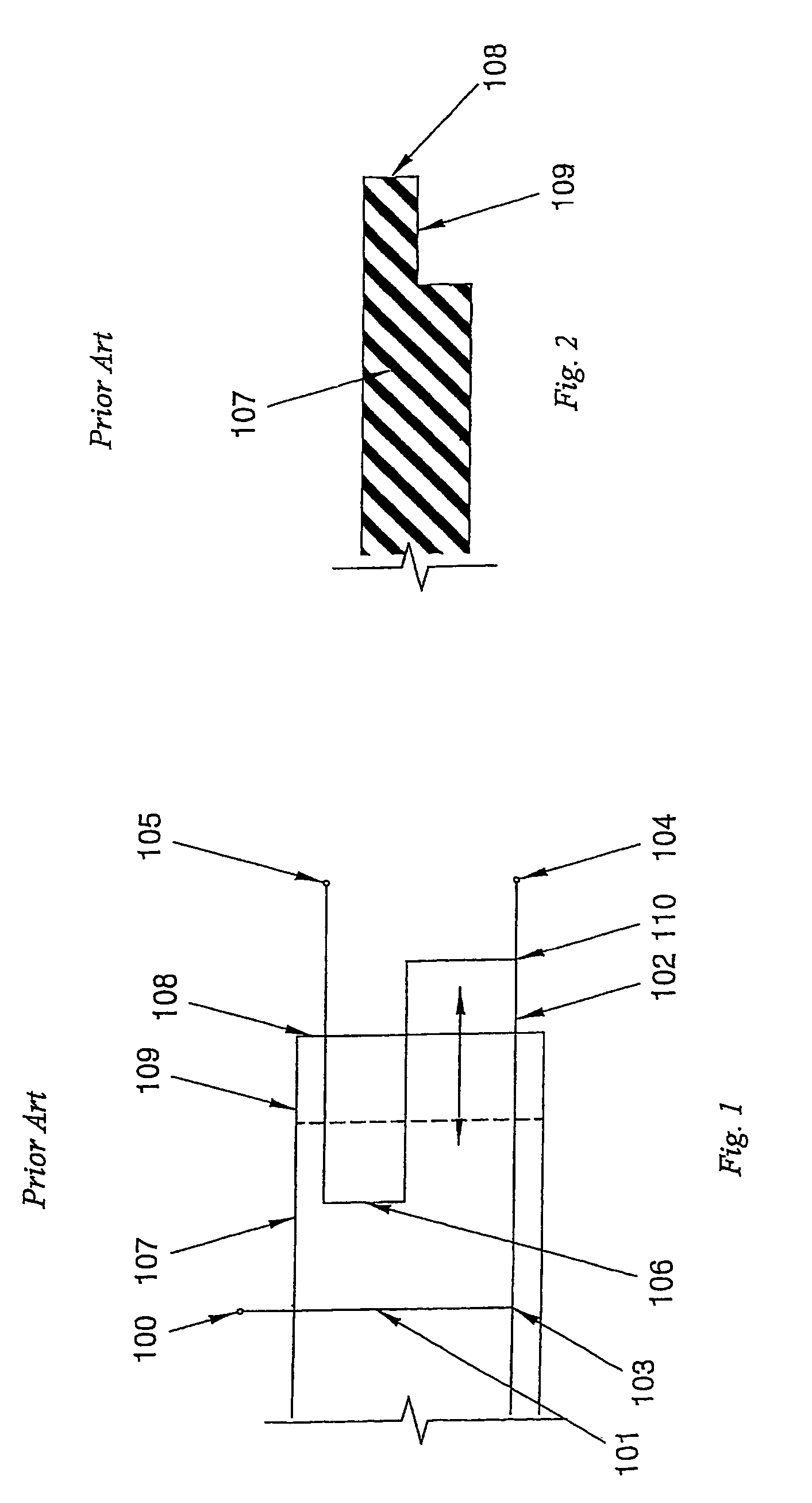
Firstly, recess 109 of the moveable dielectric body 107 operates like a transformer increasing wave impedance in the direction from input terminal 100 to the output terminals. In order to have equal impedance at the input and all outputs, the device shown in U.S. Pat. No. 5,949,303 requires additional transformers between junction 110 and output terminal 104.
Secondly, all feedlines apart from 101, which is the first from input terminal 100, cross the edge of the dielectric plate twice. Therefore the reflection at two recesses can add up to double the reflection at one recess depending on the position of the dielectric plate.
Thirdly, the relative positions of the output terminals impose constraints on the layout, which may be incompatible with physical realisations of beam-forming networks for some applications.
Fourthly, it can be difficult to accurately and consistently fabricate the recess 109 in slab 107.
Fifthly, this approach is not suitable for a linear array containing an odd number of output ports.

Method used


Image

  • Adjustable antenna feed network with integrated phase shifter
  • Adjustable antenna feed network with integrated phase shifter
  • Adjustable antenna feed network with integrated phase shifter

Examples


Embodiment Construction

[0064]In this written description, the use of the disjunctive is intended to include the conjunctive. The use of definite or indefinite articles is not intended to indicate cardinality. In particular, a reference to “the” object or thing or “an” object or “a” thing is intended to also describe a plurality of such objects or things.

[0065]The preferred arrangements described below provide a tuneable multi-channel phase shifter integrated with a beam-forming network for a linear antenna array. In order to control the beam direction and beam shape of this antenna array we need to provide certain phase relations between the radiating elements. For subsequent control and changing the beam direction these phase relations should be varied in a specific manner. The beam-forming network also includes circuit-matching elements to minimise signal reflection and maximise the emitted fields.

[0066]A 10-port feedline network with integrated phase shifter for a phased array antenna is shown in FIGS....


PUM


Abstract

A device for feeding signals between a common line and two or more ports. The device including a branched network of feedlines coupling the common line with the ports. The feedlines have transformer portions of varying width for reducing reflection of signals passing through the network. A dielectric member is mounted adjacent to the network and can be moved to synchronously adjust the phase relationship between the common line and one or more of the ports. The dielectric member also has transformer portions for reducing reflection of signals passing through the network. At least one of the junctions of the network does not overlap with the dielectric member, or overlaps a region of reduced permittivity.

Description

FIELD OF INVENTION[0001]The invention relates to a device for feeding signals between a common line and two or more ports. The invention also relates to a dielectric phase shifter and a method of manufacturing a dielectric phase shifter.BACKGROUND OF THE INVENTION[0002]Traditionally tuneable antenna elements consist of power splitters, transformers, and phase shifters cascaded in the antenna arrangement. In high performance antennas these components strongly interact with each other, sometimes making a desirable beam shape unrealisable.[0003]A number of canonical beam-forming networks have been proposed in the past, to address these problems.[0004]FIG. 1 is a plan view of part of a phase shifter described in U.S. Pat. No. 5,949,303. An input terminal 100 is coupled to an input feedline 101. A feedline 102 branches off from junction 103 and leads to a first output terminal 104. A second output terminal 105 is coupled to feedline 102 at junction 110 by a meander-shaped loop 106. A die...

Claims


Application Information

Patent Timeline
IPC IPC(8): H01P5/12H01P1/18H01P3/08H01P5/02H01P5/04H01Q1/24H01Q1/46H01Q3/32H01Q21/06
CPCH01Q1/246H01Q21/06H01Q3/32H01Q3/30
Inventor SLEDKOV, VICTOR ALEKSANDROVICH
Owner COMMSCOPE TECH LLC
Learn More