Magnetically enhanced convection heat sink

a heat sink and magnetic enhancement technology, applied in the field of heat sinks, can solve the problems of major concern in the dissipation of heat from electrical and electronic systems and devices, affecting cost and performance in the electronic industry, and affecting the cooling effect of electronic devices, so as to enhance the convection cooling of electronic devices, enhance the flow of air, and no power consumption

Inactive Publication Date: 2006-04-18
THE BOEING CO
View PDF12 Cites 144 Cited by
  • Summary
  • Abstract
  • Description
  • Claims
  • Application Information

AI Technical Summary

Benefits of technology

[0006]The invention is directed to an apparatus and method for enhancing convection cooling of electronic devices by exploiting the paramagnetic property of air. Air is paramagnetic, i.e., it is attracted to a magnet, and cool air is attracted to a magnet more strongly than hot air. The invention makes use of these properties in a heat sink that produces a magnetic gradient to enhance the flow of air past and away from a heat sink member. The invention is an improvement over current approaches for removing heat from circuits where simple convection is inadequate. Unlike fans or heat pipes, a preferred heat sink of the present invention using permanent magnets to create a magnetic gradient and magnetic driving force has no vibration, no acoustic noise, no electromagnetic interference, no power consumption, and no bearings or moving parts. It has no toxic materials and fits onto an electronic package in much the same way as a conventional heat sink. It also reduces the weight, volume, and failure rate of electronic assemblies. The heat sink of the invention can be configured to accommodate various applications.

Problems solved by technology

Dissipating heat from electrical and electronic systems and devices is a technical issue affecting cost and performance throughout the electronic industry.
With respect to the aerospace industry in particular, where the use of electronic devices is prevalent, the problem of dissipating heat from these devices is of major concern due to the limitations on space and available power.
Radiation is inefficient at low and moderate temperatures such as those encountered aboard the International Space Station or other space craft.
Conduction is usually inefficient, and even when efficient it imposes a mass penalty in the form of metal conduction paths.
Forced convection requires the use of power which is at a premium in many aerospace and other applications, and often generates undesirable vibration and noise.
Heat pipes usually cannot be used within an electronics assembly.
In many cases, conduction through the air is insignificant, and radiant heat rejection is often insufficient when temperatures are kept within the operating temperature range of most electronics.
This increases the heat generated per unit area.
However, cooling fans add noise, cost, weight, and power usage, and represent one of the major sources of failure in modern avionics.
However, the requisite fluid pumps, hoses, and chillers add greatly to system mass, cost, and maintenance needs.
The problem of providing sufficient convection is particularly acute where the electronics are operating in a microgravity environment, such as an orbiting space craft, where gravity-driven convection is not present.

Method used


Image

  • Magnetically enhanced convection heat sink
  • Magnetically enhanced convection heat sink
  • Magnetically enhanced convection heat sink

Examples


Embodiment Construction

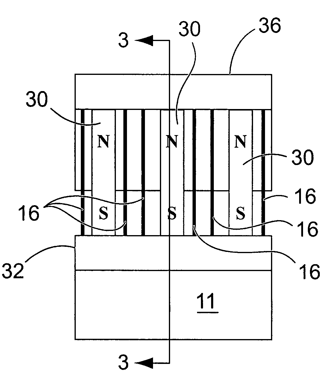
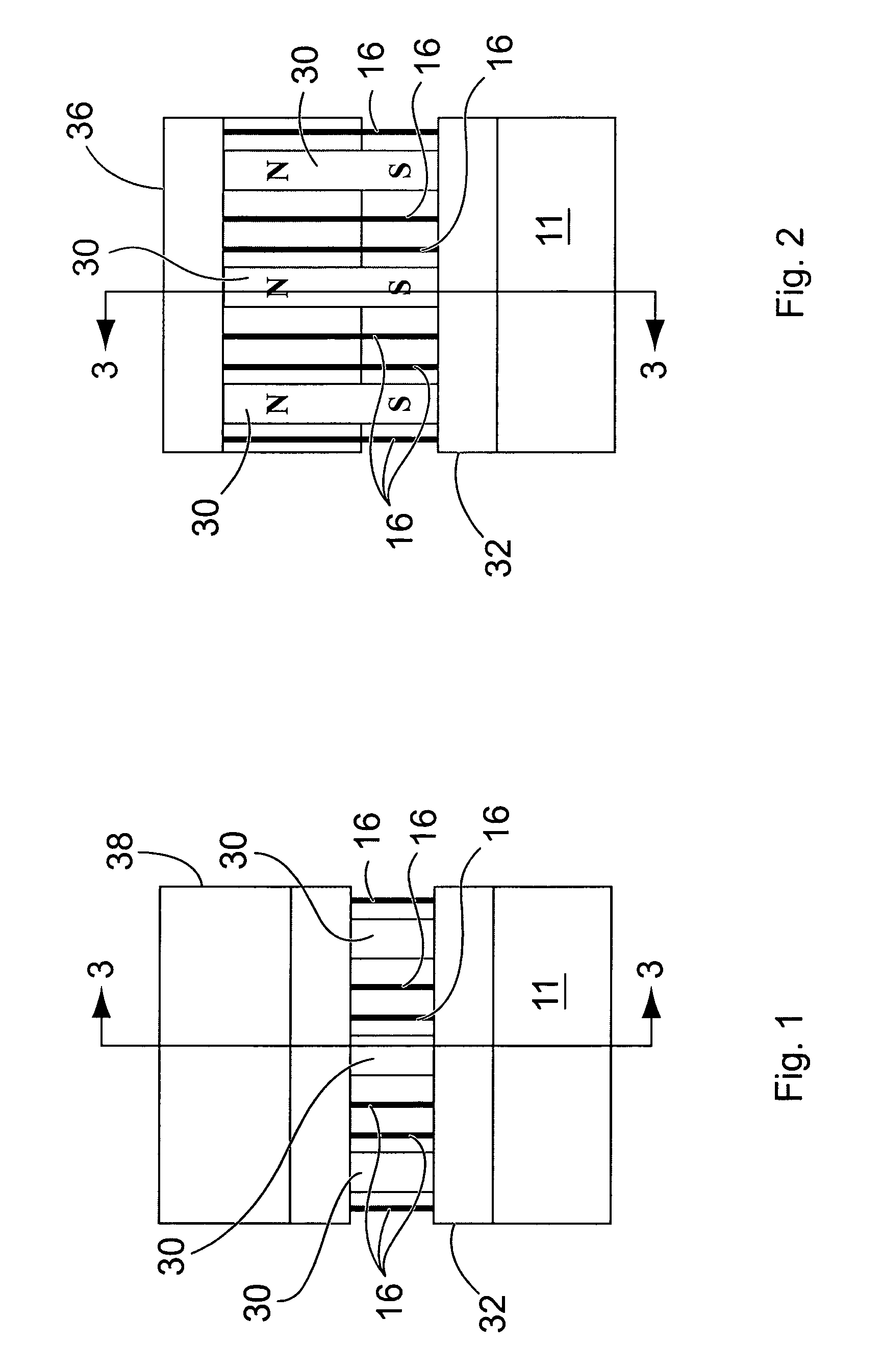
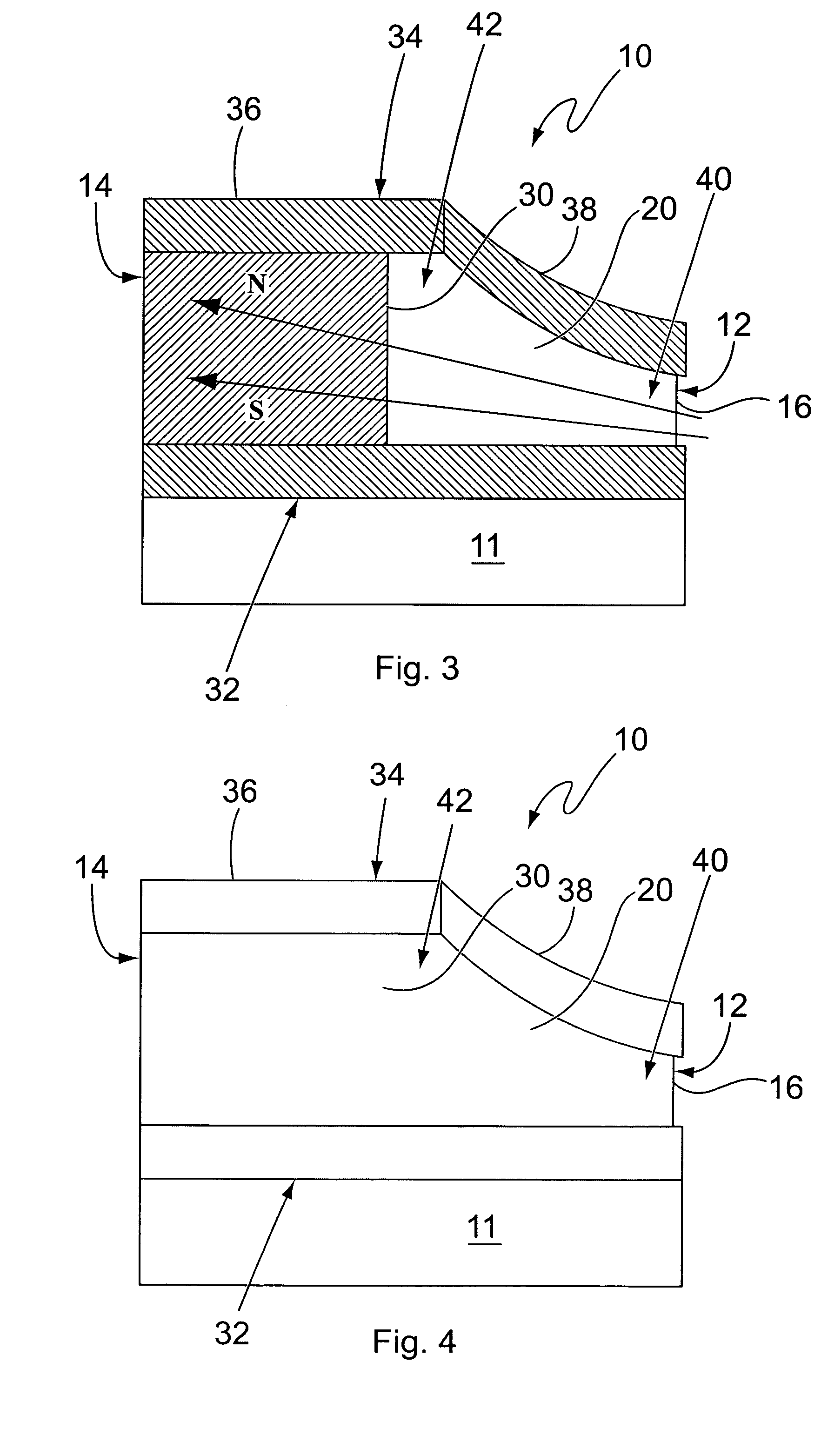
[0019]With reference to the drawing, there is shown a magnetically enhanced convection heat sink 10 in accordance with a preferred embodiment of the invention for dissipating heat from a heat source 11 which may be an electronic device. The heat sink 10 comprises a heat sink member 12 and magnetic source 14. The heat sink member 12 includes a plurality of fins 16 arranged in parallel spaced apart relationship as shown. Each fin has major side surfaces 20. The fins are essentially thin sheets, as is customary with conventional, non-magnetically enhanced heat sinks, to provide large surface areas in contact with the air without requiring large mass. The thickness of the fins depends on the particular application taking into account the physical size of the heat sink, the heat flux through each fin, and the mechanical stress exerted on the fins. Thus, depending on the particular application for the heat sink, the fins may be of a foil thickness, or substantially thicker and more substa...


PUM

PropertyMeasurementUnit
boiling pointaaaaaaaaaa
Curie temperatureaaaaaaaaaa
paramagnetic propertiesaaaaaaaaaa

Abstract

A magnetically enhanced convection heat sink comprises a heat sink member for dissipating heat from a heat source. A magnetic source creates a magnetic field concentrated at a first location, the intensity of the magnetic field decreasing from the first location to a second location. The heat sink member is positioned within the magnetic field and in a gas flow path between the first and second locations. Gas, having paramagnetic properties, entering the heat sink at the first location is heated by the heat sink member, and as the gas becomes warmer is displaced by cooler gas causing the warmer gas to move toward the second location as it is further heated by the heat sink.

Description

BACKGROUND OF THE INVENTION[0001]This invention is directed to a heat sink, and more specifically a heat sink for dissipating heat from a heat source by magnetically enhanced convection.[0002]Dissipating heat from electrical and electronic systems and devices is a technical issue affecting cost and performance throughout the electronic industry. With respect to the aerospace industry in particular, where the use of electronic devices is prevalent, the problem of dissipating heat from these devices is of major concern due to the limitations on space and available power. In the absence of gravity aboard orbiting spacecraft, heat dissipation must rely on radiative or conductive transport, forced convection, or heat pipes. Radiation is inefficient at low and moderate temperatures such as those encountered aboard the International Space Station or other space craft. Conduction is usually inefficient, and even when efficient it imposes a mass penalty in the form of metal conduction paths....

Claims


Application Information

Patent Timeline
Patent Type & Authority Patents(United States)
IPC IPC(8): H05K7/20F28F13/00H01F7/02H01F7/20H01F13/00H01L23/467
CPCF28F13/00H01L23/467H01F7/0273H01F7/20H01F13/00H01L2924/0002H01L2924/00
Inventor TILLOTSON, BRIAN J.
Owner THE BOEING CO
Why Eureka
Try Eureka