Fully digital AGC circuit with wide dynamic range and method of operation

a fully digital, agc circuit technology, applied in the field of alldigital automatic gain control (agc) circuits, can solve the problems of inability to achieve the desired dynamic range over a wide dynamic range, instability of analog agc circuits, and inability to achieve the dynamic range of analog agc loops, etc., to achieve the effect of reducing the number of processing elements required

Inactive Publication Date: 2006-04-18
SAMSUNG ELECTRONICS CO LTD
View PDF9 Cites 27 Cited by
  • Summary
  • Abstract
  • Description
  • Claims
  • Application Information

AI Technical Summary

Benefits of technology

[0013]The present invention provides an automatic gain control (AGC) circuit implemented entirely in digital circuitry that greatly minimizes the processing elements required. The present invention is optimized for implementation in a field programmab

Problems solved by technology

The accuracy of an analog AGC circuit is often acceptable over a narrow dynamic range, but is often less than desirable over a wide dynamic range.
Additionally, the dynamic range of analog AGC circuit is often limited by stability.
Analog AGC loops also exhibit poor accuracy, poor temperature variation characteristics, wide variations with device characteristics, sensitivity to signal modulation characteristics, sensitivity to signal crest factor, sensitivity to the number of received carriers, and limited capability for programmable time constant.
However, digital receivers are often required to process signals received over a wide range of intensities, while the digital demodulator circuits within digital receivers perform optimally only over a relatively narrow range of signal intensities.
However, full digital AGC implementations have proved difficult due to the need to replace the variable gain analog element with a wide-bit multiplier in the dig

Method used


Image

  • Fully digital AGC circuit with wide dynamic range and method of operation
  • Fully digital AGC circuit with wide dynamic range and method of operation
  • Fully digital AGC circuit with wide dynamic range and method of operation

Examples


Embodiment Construction

[0032]FIGS. 1 through 3, discussed below, and the various embodiments used to describe the principles of the present invention in this patent document are by way of illustration only and should not be construed in any way to limit the scope of the invention. Those skilled in the art will understand that the principles of the present invention may be implemented in any suitably arranged wireless network.

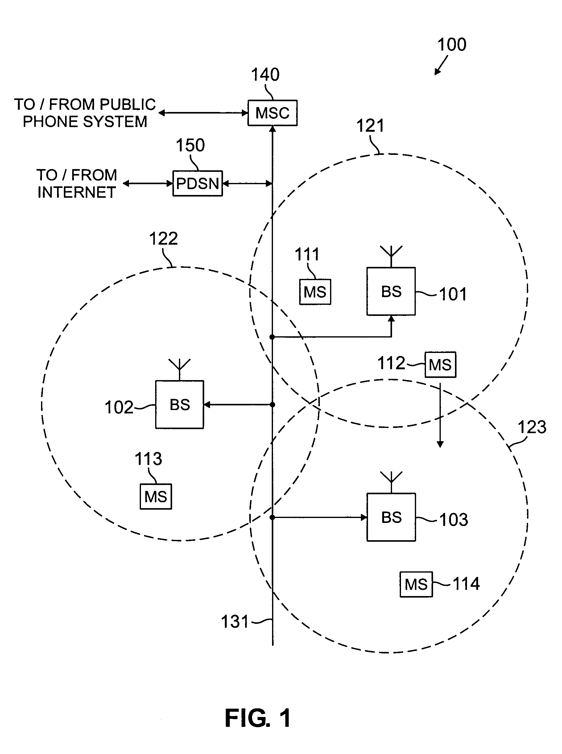
[0033]FIG. 1 illustrates exemplary wireless network 100 according to one embodiment of the present invention. Wireless network 100 comprises a plurality of cell sites 121–123, each containing one of the base stations, BS 101, BS 102, or BS 103. Base stations 101–103 communicate with a plurality of mobile stations (MS) 111–114 over, for example, code division multiple access (CDMA) channels. Mobile stations 111–114 may be any suitable wireless devices, including conventional cellular radiotelephones, PCS handset devices, personal digital assistants, portable computers, or metering devi...


PUM


Abstract

A digital automatic gain control (AGC) circuit for use in a radio frequency (RF) receiver. The AGC circuit comprises: 1) a first shifter for receiving an in-phase signal as a first series of X-bit samples and left-shifting each X-bit sample by a number of bits determined by a coarse scaling factor; 2) a first limiter for receiving the D most significant bits of the output of the first shifter and outputting a subset of the D most significant bits of the first shifter output; 3) a first multiplier for multiplying the subset of the D most significant bits of the first shifter output by a fine scaling factor to produce a first M-bit product; and 4) a gain adjustment circuit for comparing a power signal derived from the first M-bit product to a maximum threshold value and generating the coarse scaling factor and the fine scaling factor.

Description

TECHNICAL FIELD OF THE INVENTION[0001]The present invention is directed, in general, to radio frequency (RF) receivers and, more specifically, to an all-digital automatic gain control (AGC) circuit for use in the receiver of a wireless network base station or the receiver of a wireless access terminal.BACKGROUND OF THE INVENTION[0002]Conventional automatic gain control (AGC) circuits are analog circuits consisting of variable gain amplifiers and / or attenuators driven by a signal level detection circuit and an integrator circuit. The accuracy of an analog AGC circuit is often acceptable over a narrow dynamic range, but is often less than desirable over a wide dynamic range. Additionally, the dynamic range of analog AGC circuit is often limited by stability. Analog AGC loops also exhibit poor accuracy, poor temperature variation characteristics, wide variations with device characteristics, sensitivity to signal modulation characteristics, sensitivity to signal crest factor, sensitivit...

Claims


Application Information

Patent Timeline
IPC IPC(8): H04L27/08H04L27/38
CPCH04L27/3809H04L27/08
Inventor BROBSTON, MICHAEL L.ROCK, JASONYOON, WEON-KIJEON, MIN
Owner SAMSUNG ELECTRONICS CO LTD
Why Eureka
Try Eureka