

Organic light emitting device with reverse intersystem crossing light emitting molecules
a light-emitting device and reverse-intersystem technology, applied in the direction of organic semiconductor devices, discharge tubes luminescnet screens, natural mineral layered products, etc., can solve the problems of triplet annihilation, no material of which practical use is in prospect, and high cost of iridium-based iridium complexes
- Summary
- Abstract
- Description
- Claims
- Application Information
AI Technical Summary
Benefits of technology
Problems solved by technology
Method used
Image

Examples
example 1
[0249]Compound of Formula 4 that has an isobenzothiophene structure of Formula 3 as a central backbone was designed by computer simulation. The software used for the simulation and conditions are as described above.
[0250]
[0251]The energy level of each excited state was expected as follows.
[0252]
S12.6492 eVT11.6129 eVT22.9561 eVS1 oscillator strength0.4318
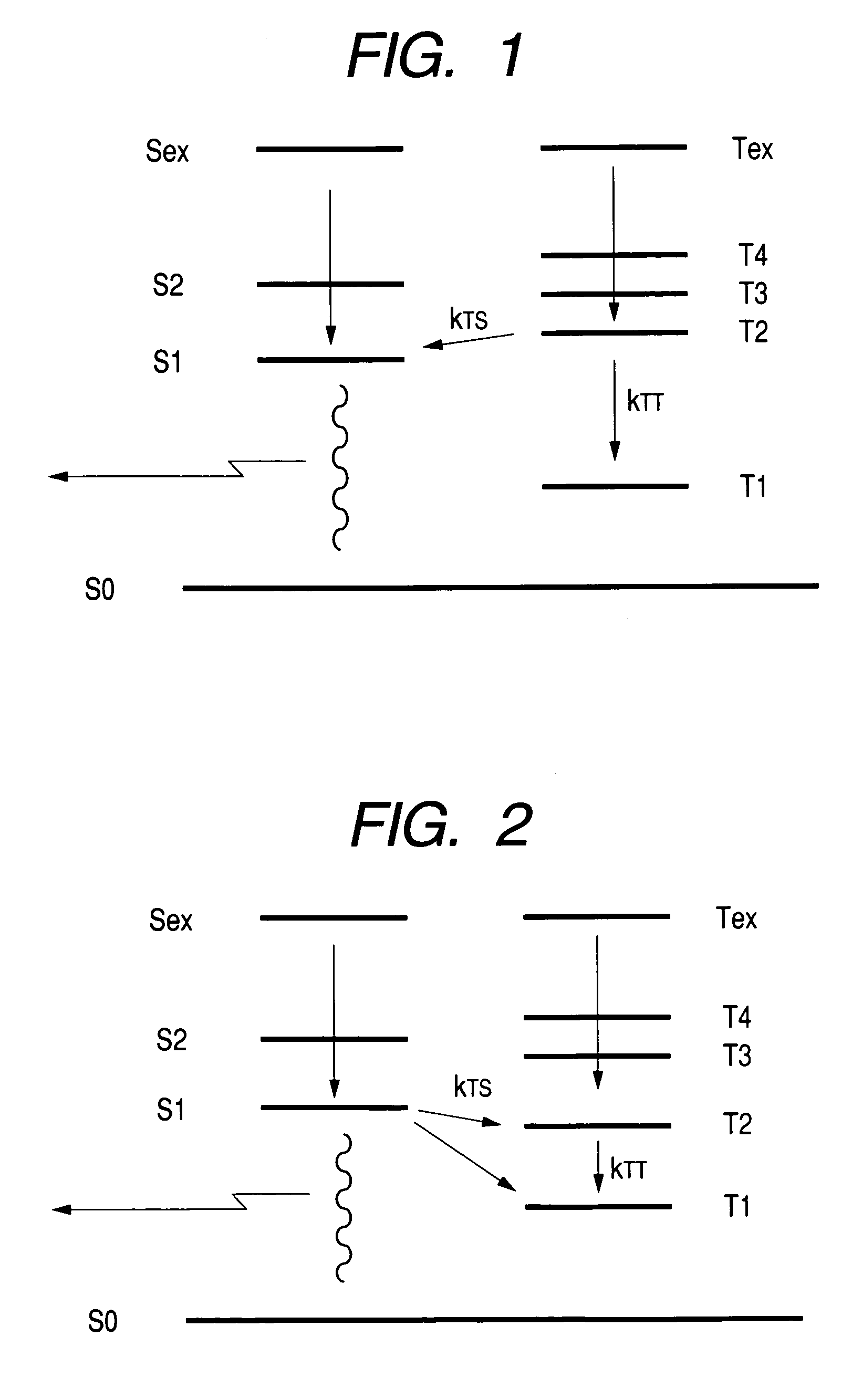
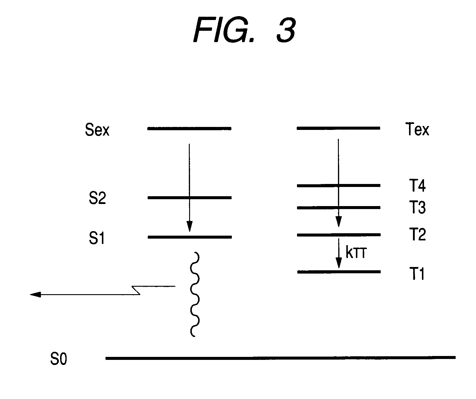
[0253]T1–T2 gap is as large as 1.3432 eV, and is over 1.3 eV. T2>S1 is fulfilled and T2 is higher than S1 by 0.3069 eV. S1 oscillator strength has a sufficient value.
[0254]Substituents have a mesityl group and a phenyl group that are bonded to boron or nitrogen in the shape of a trident, respectively, and these mesityl and phenyl groups are further twisted around each other thereby realizing a bulky structure.[0255]HOMO level is −4.9489 eV; and[0256]LUMO level is −1.9431 eV
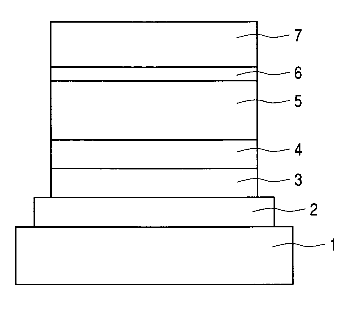
and good charge injection properties can be expected by combining with an electron transporting layer by a suitable electron transporting material and a hole tran...
example 2
[0277]A second example of this invention is described below.
[0278]The compound of the following Formula 8 was designed by computer simulation which had the benzothiazole represented by Formula 7 as a central backbone. The software and conditions used for the simulation are as stated above.
[0279]
[0280]The energy level of each excited state was expected as follows.
[0281]
S12.7946 eVT11.9273 eVT22.9401 eVS1 oscillator strength0.1190
Although T1–T2 gap is 1.0128 eV and does not exceed 1.3 eV, it is also large.[0282]T2>S1 is fulfilled and T2 is higher than S1 by 0.1455 eV.[0283]S1 oscillator strength has sufficient value.
[0284]The substituent has an amino group bonded to nitrogen to realize a bulky structure.[0285]HOMO level is −4.9907 eV; and[0286]LUMO level is −1.6861 eV, and good charge injection properties can be expected by combining with an electron transporting layer of a suitable electron transporting material, and a hole transporting layer of a suitable hole transporting material....
PUM
| Property | Measurement | Unit |
|---|---|---|
| Fraction | aaaaa | aaaaa |
| Fraction | aaaaa | aaaaa |
| Fraction | aaaaa | aaaaa |
Abstract
Description
Claims
Application Information