Multi-fuel compression ignition engine

Inactive Publication Date: 2006-05-02
CLEAN AIR POWER
View PDF18 Cites 78 Cited by
  • Summary
  • Abstract
  • Description
  • Claims
  • Application Information

AI Technical Summary

Benefits of technology

[0016]The primary fuel preferably is supplied in a homogenous charge to obtain HCCI of the liquid fuel. To make this possible, the primary fuel is supplied in the form of finely atomized droplets having a mean diameter of less than about 50 microns, and more preferably less than about 30 microns, and even more preferably between about 5 microns and 20 microns. Droplets of this size

Problems solved by technology

One drawback of gaseous fuels is that they exhibit significantly higher ignition threshold temperatures than do diesel fuel, lubricating oil, and other liquid fuels traditionally used in compression ignition engines.
The compression temperature of the gas and air mixture is insufficient during operation of standard compression ignition engines for autoignition.
.), particularly if the pilot fuel injectors are too small to permit the use of the engine in diesel-only mode.
A disadvantage of dual fuel engines over spark-ignited engines is the potential generation of increased quantities of oxides of Nitrogen (NOX) resulting from sub-maximum ignition intensity of the pilot fuel charge and resultant less than optimal combustion of the pilot and gas fuel charges.
As a result, overly rich air/fuel mixtures are co

Method used


Image

  • Multi-fuel compression ignition engine
  • Multi-fuel compression ignition engine
  • Multi-fuel compression ignition engine

Examples


Embodiment Construction

1. Resume

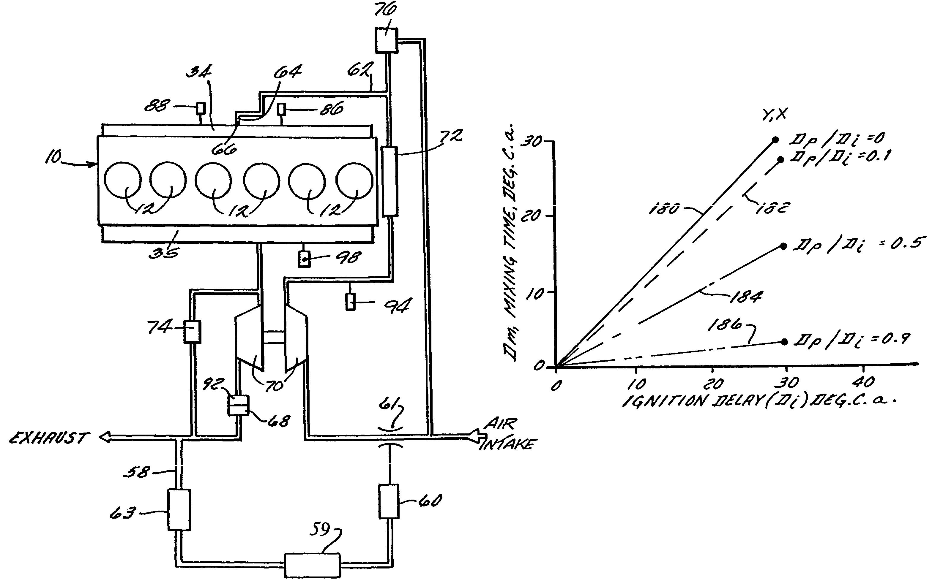
[0040]Pursuant to the invention, pilot fuel injection and / or ignition are controlled in a pilot ignited compression ignition engine so as to maintain a relationship Dp / Di of <1, where Dp is the duration of the pilot fuel injection event and Di is the ignition delay period, as measured from the start of initiation of pilot fuel injection (Tp) to the start of pilot fuel autoignition (Ti). Although this control proceeds contrary to conventional wisdom, the inventors have discovered that the mixing period (Dm) resulting from maintaining an ignition delay period that is longer than an injection period maximizes ignition intensity by permitting the injected pilot fuel to become thoroughly distributed through and mixed with the second fuel in the combustion chamber prior to ignition. This, in turn, results in improved premixed burning of a nearly homogeneous mixture of the pilot fuel, the second fuel, and air and dramatically reduced NOx emissions. The second fuel may be either a ...


PUM


Abstract

A liquid primary fuel is ignited by HCCI with the assistance of the early injection of a liquid pilot fuel. Pilot fuel injection and/or ignition are preferably controlled so as to permit the injected pilot fuel to become thoroughly distributed through and mixed with the primary fuel/air charge in the combustion chamber and vaporized prior to ignition. Pilot fuel having a lower autoignition temperature will be ignited by compression ignition, followed by the ignition of the homogeneous mixture of the primary fuel and air. HCCI combustion of the primary fuel is facilitated by 1) selection of the properties of the primary and pilot fuels and 2) obtaining a homogenous mixture of primary fuel and air by injecting primary fuel into the engine's intake air stream in the form of finely atomized droplets having a mean diameter in the micron range.

Description

CROSS REFERENCE TO RELATED APPLICATION[0001]This application is a continuation-in-part of U.S. patent application Ser. No. 09 / 791,195; filed Feb. 23, 2001 now U.S. Pat. No. 6,598,584, that is entitled Gas-Fueled, Compression Ignition Engine with Maximized Pilot Ignition Intensity, the entire disclosure of which is incorporated herein by reference.BACKGROUND OF THE INVENTION[0002]1. Field of the Invention[0003]The present invention relates generally to multi-fuel engines and, more specifically, to a compression ignition engine powered at least partially by a first fuel pilot ignited by a second fuel having a lower auto-ignition temperature.[0004]2. Discussion of the Related Art[0005]Recent years have seen an increased demand for the use of gaseous fuels as a primary fuel source in compression ignition engines. Gaseous fuels such as propane or natural gas are considered by many to be superior to diesel fuel and the like because gaseous fuels are generally less expensive, and when used...

Claims


Application Information

Patent Timeline
IPC IPC(8): F02B3/00F02B1/12F02B37/00F02B3/06F02B23/06F02B37/18F02B37/24F02B75/18F02D1/02F02D15/04F02D19/02F02D19/08F02D19/10F02D19/12F02D21/08F02D23/00F02D41/00F02D41/02F02D41/38F02D41/40F02D43/00F02M21/02F02M25/07F02M31/20F02M61/18
CPCF02B1/12F02B23/0651F02B23/0672F02D19/0631F02D19/10F02D41/0027F02D41/403F02D19/061F02D19/0689Y02T10/36F02B23/06F02B23/0603F02B23/0621F02B23/0624F02B29/0406F02B2075/1824F02D41/0047F02M25/0709F02M25/0713F02M25/0727F02M25/074Y02T10/125Y02T10/128Y02T10/44F02B3/06F02M26/06F02M26/10F02M26/23F02M26/35Y02T10/12Y02T10/30Y02T10/40
Inventor BECK, NIELS JOHANNESGEBERT, KRESIMIRWONG, HOI-CHING
Owner CLEAN AIR POWER
Why Eureka
Try Eureka