Low-temperature formation method for emitter tip including copper oxide nanowire or copper nanowire and display device or light source having emitter tip manufactured using the same
- Summary
- Abstract
- Description
- Claims
- Application Information
AI Technical Summary
Benefits of technology
Problems solved by technology
Method used
Image
Examples
first embodiment
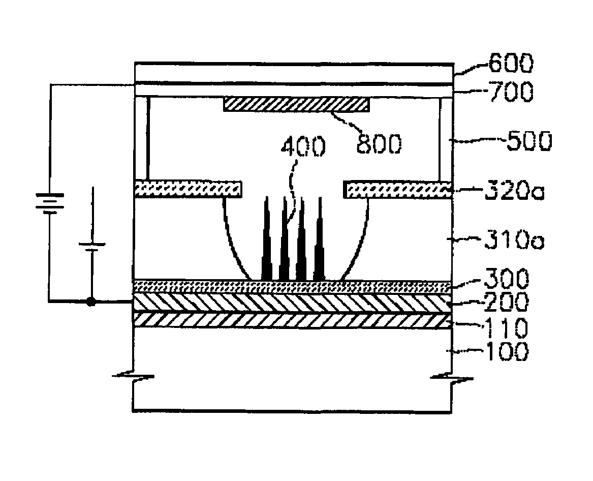
[0051]FIGS. 7 through 9 are cross-sectional views illustrating a method of manufacturing an FED using the low-temperature formation method for emitter tips including copper oxide nanowires or copper nanowires according to the present invention, according to another embodiment of the present invention. The same formation methods, thickness, shape, size, and material of elements as in the first embodiment will not be repeated here.
[0052]Referring to FIG. 7, unlike in the first embodiment, before a copper layer is formed, a cathode electrode 200, an insulating layer 310, a metal layer 320 for a gate electrode, and a photoresist pattern PR are sequentially formed on a large-sized lower substrate 100. The metal layer 320 for the gate electrode and the insulating layer 310 are sequentially etched using the photoresist pattern PR as an etch mask, thereby forming a gate electrode 320a and an insulating pattern 310a. As a result, the surface of the cathode electrode 200 is exposed.
[0053]Refe...
third embodiment
[0060]FIGS. 12 through 14 are cross-sectional views illustrating a method of manufacturing a white light source using the low-temperature formation method of the present invention, according to further another embodiment of the present invention. The present embodiment differs from the third embodiment in that emitter tips 400 are grouped into several groups and each group constitutes one cell.
[0061]Referring to FIG. 12, a first insulating layer 110, a cathode electrode 200, a copper layer 300, and a second insulating layer 310 are sequentially formed on a lower substrate 100 and patterned using photolithography and etching processes, thereby forming a second insulating pattern 310a. The second insulating pattern 310a defines a plurality of holes H, which expose the copper layer 300. Here, the second insulating pattern 310a is formed such that each of the holes H has a diameter and an interval suitable for defining a cell.
[0062]Referring to FIG. 13, copper oxide nanowires are formed...
PUM
 Abstract
Description
Claims
Application Information
 - R&D
- Intellectual Property
- Life Sciences
- Materials
- Tech Scout
- Unparalleled Data Quality
- Higher Quality Content
- 60% Fewer Hallucinations
Browse by: Latest US Patents, China's latest patents, Technical Efficacy Thesaurus, Application Domain, Technology Topic, Popular Technical Reports.
© 2025 PatSnap. All rights reserved.Legal|Privacy policy|Modern Slavery Act Transparency Statement|Sitemap|About US| Contact US: help@patsnap.com


