Variable speed distributed drive train wind turbine system

a distributed drive and wind turbine technology, applied in the direction of electric generator control, dynamo-electric converter control, instruments, etc., can solve the problems of increasing the torque of the main shaft, the inability to respond adequately to wind gusts, and the significant impact of the cost of wind generated electricity, so as to achieve high total drive train efficiency and high efficiency. , the effect of high efficiency

Inactive Publication Date: 2006-05-09
UNITED TECH CORP
View PDF63 Cites 265 Cited by
  • Summary
  • Abstract
  • Description
  • Claims
  • Application Information

AI Technical Summary

Benefits of technology

[0013]An advantage of the invention is that the power conversion system is a unidirectional passive rectifier / active inverter. The passive rectifier permits a higher efficiency than previous active rectifiers. This conversion system together with a high efficiency synchronous generator provide for very high total drive train efficiency. In the multiple generator implementation described herein, efficiency is further enhanced at low power levels by staging generators and allowing these generator to operate at or near their optimal efficiency.
[0014]A further advantage of the invention is that the power conversion system or GCU is capable of responding to torque commands from the TCU and providing the requested torque without the use of any field orientation or other sophisticated control algorithm. The simplicity of this approach allows the converter to control the generator torque without the use of a generator position encoder or generator speed tachometer, which enhances reliability and eliminates tachometer related failure modes. In fact the use of synchronous generators allows the generator to be used as a system tachometer. In this capacity with multiple generators, a secondary, redundant tachometer is inherently provided as required by codes and certification bodies using only the generators already a part of the system.
[0015]The invention also allows for main-shaft damping without the use of a generator tachometer. Because synchronous generators are used with a passive rectifier, the main-shaft resonant frequency due to blade inertia, compliant main-shaft inertia and bull gear inertia, can be sensed in the DC link voltage. The DC bus voltage is monitored and passed through a band pass filter which is tuned at the main-shaft resonant frequency. The filtered signal can then be scaled and applied to the inverter system torque command and active damping is achieved.
[0016]In accordance with an aspect of the invention, the inverter runs at a fixed power factor angle near, or at unity, and is not controllable. This is advantageous as operating the wind turbines at a unity power factor reduces the balance of system costs such as the cable running to the turbines within a wind plant. For conditions where wind plant power factor needs to be varied dynamically, the function is performed with a separate power factor apparatus at the substation connection of a group of turbines. This provides the lowest-cost wind-plant design, as there is no over sizing of in-plant balance of system items such as pad-mount transformers and conductors. This normal increased-sized requirement is moved to the substation. With this turbine design there is no incremental cost associated with a requirement for over-sized conductors and transformers.
[0017]In accordance with an aspect of the invention the large, protection coordinated, synchronous reactance in the generators prevent high fault currents from occurring and significantly simplify the protective functions associated with running DC pendant cables down the tower. In the past, DC pendant cables were dismissed because of the prohibitive cost of protective switchgear and functions created by high power DC power transfer. The high reactance (300% fault current for a 33% synchronous reactance) fundamentally limits the available fault current and DC pendant cables become practical. Careful co-ordination of the generators' reactance and DC pendant cable sizing permit the transfer of high power over DC pendant cables and reduce the total amount of copper being used in the pendant cables. Thus power may be generated and rectified in the nacelle and the rest of the power conversion system may be placed at the base of the tower.
[0018]In accordance with a further aspect of the invention, the TCU controls the turbine blade pitch angle via the Pitch Control Unit (PCU) as well as the generator torque via the Generator Control Unit (GCU). The TCU provides a complicated, coordinated control function to both of these elements, and does so in a way, which maximizes the energy capture of the turbine while minimizing the mechanical loads. A description of how this is accomplished is provided in the detailed description. The TCU uses many necessary inputs to complete this coordination function between torque and pitch. Typical TCU inputs include turbine speed, blade pitch angle, tower acceleration (vibration), nacelle acceleration (nacelle vibration), wind speed, wind direction, wind turbulence, nacelle position, AC line parameters, DC bus voltage, generator voltage, power output, reactive power output, and others. Loads which are controlled and mitigated by the TCU include tower vibration, nacelle vibration, generator torque, and blade loads.A summary of advantages of the present invention include:

Problems solved by technology

The development of practical, wind-powered generating systems creates problems, which are unique and not encountered in the development of conventional power generating systems.
These issues together with mechanical fatigue due to wind variability have a significant impact on the cost of wind generated electricity.
Because of stability considerations, this control loop must be operated with a limited bandwidth and, thus, is not capable of responding adequately to wind gusts.
In this condition, main-shaft torque goes up and transient power surges occur.
These power surges not only affect the quality of the electrical power produced, but they create significant mechanical loads on the wind turbine itself.
These mechanical loads further force the capital cost of turbines up because the turbine structures must be designed to withstand these loads over long periods of time, in some cases 20–30 years.

Method used


Image

  • Variable speed distributed drive train wind turbine system
  • Variable speed distributed drive train wind turbine system
  • Variable speed distributed drive train wind turbine system

Examples


Embodiment Construction

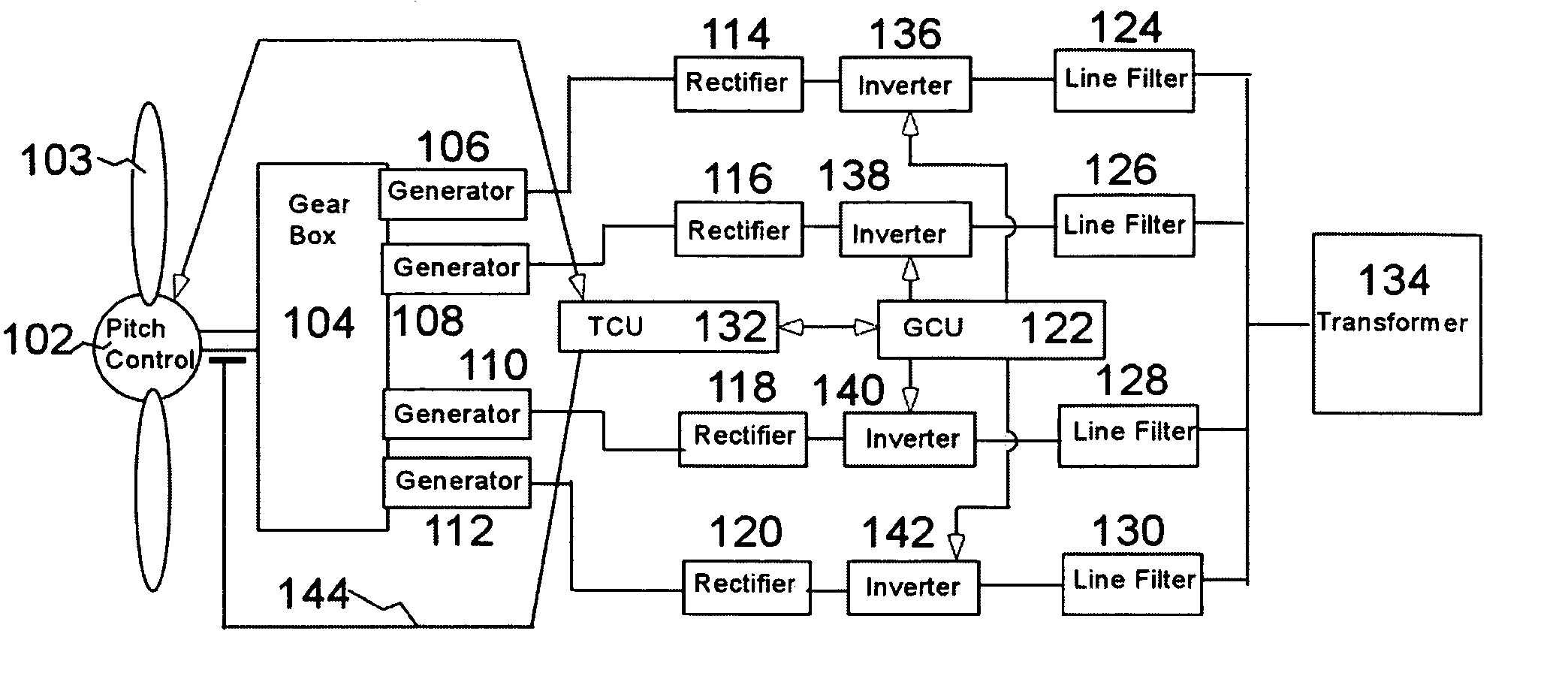
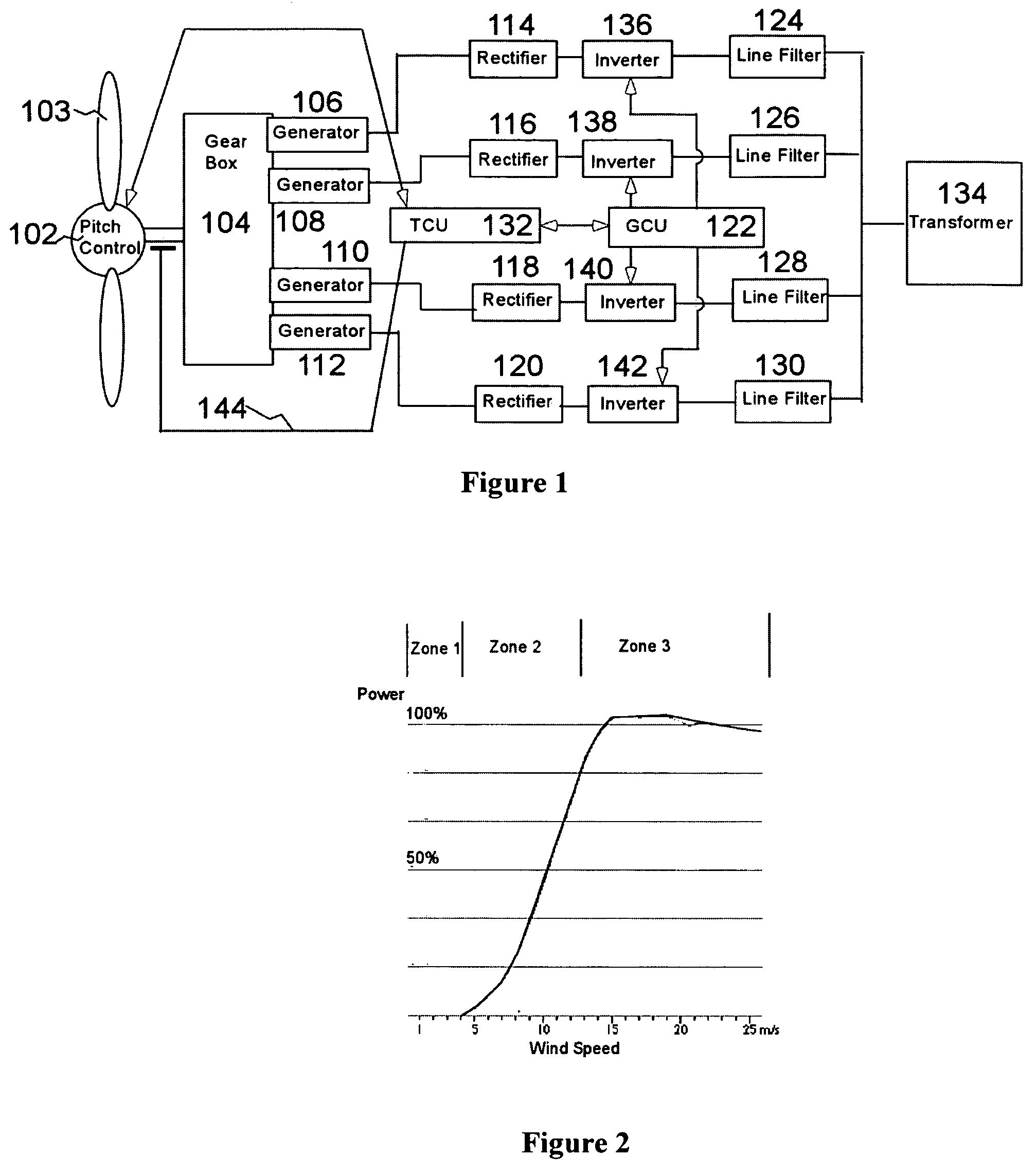
[0037]The variable-speed wind-turbine generator system is broadly shown in FIG. 1. There are six basic components of the system: Firstly a turbine drive train including a rotor hub mounted pitch servo system or PCU 102, blade rotor 103, distributed generation gearbox 104 and four permanent magnet generators 106, 108, 110, 112; secondly generator rectifier units 114, 116, 118, 120; thirdly a control system comprising a generator control unit (GCU) 122 and a turbine control unit (TCU) 132; fourthly four independent inverters, 136, 138, 140, and 142; fifthly individual line filters for each converter, 124, 126, 128, 130; and sixthly a pad-mount transformer, 134. Additionally shown in FIG. 1 is a sensor for measuring turbine speed on the low speed shaft, 144. It should be noted that for the purposes of illustration a system using four independent power conversion systems including generator, filter, inverter, rectifier, etc. is illustrated herein. A turbine using a greater or smaller nu...


PUM


Abstract

A variable speed wind turbine employing a rotor connected to a multiplicity of synchronous generators with wound field or permanent magnet rotors. A passive rectifier and an inverter are used for power transfer back to the grid. A Turbine Control Unit (TCU) commands a required generator torque based on rotor speed and power output of the turbine inverters. Torque is controlled by regulating the DC current by control of the inverter. A main-shaft-damping filter is provided by measurement of the DC bus voltage. In high winds the turbine remains at a constant average output power through a constant torque command and a varying pitch command to a rotor pitch servo system. A set point is fixed at the inverter output such that output VAR load is minimized running the turbine at very nearly unity power factor. Dynamic VAR and power factor control is provided by a separate VAR apparatus.

Description

CROSS-REFERENCE TO RELATED APPLICATIONS[0001]This application claims priority under 35 U.S.C. § 119(e) to U.S. Provisional Patent Application No. 60 / 468,899 Variable Speed Wind Turbine Technology, which was filed on May 7, 2003 and which is incorporated herein by reference.[0002]This application is related to U.S. Pat. No. 6,304,002; U.S. Pat. No. 6,731,017; U.S. Pat. No. 6,653,744; U.S. patent application Ser. No. 10 / 426,287 of Kevin L. Cousineau entitled “Distributed Static VAR Compensation (DSVC) System For Wind And Water Turbine Applications” filed Apr. 30, 2003, and U.S. patent application Ser. No. 10 / 449,342 of Amir S. Mikhail and Edwin C. Hahlbeck entitled “Improved Distributed Power Train (DGD) with Multiple Power Paths” filed May 31, 2003, all of which are assigned to Clipper Windpower Technology, Inc. and are incorporated herein by reference.BACKGROUND OF THE INVENTION[0003]1. Field of the Invention[0004]The invention relates to fluid-flow turbines, such as wind turbines u...

Claims


Application Information

Patent Timeline
Patent Type & Authority Patents(United States)
IPC IPC(8): H02P9/00F03D7/00F03D9/00G05D11/00H02J3/00F03D7/02F03D7/04H02H7/06H02P5/747H02P9/02H02P9/04H02P11/00
CPCF03D7/0224F03D7/0276F03D7/028F03D7/0284F03D7/042F03D7/048F03D9/002F03D9/003H02P5/747H02P9/02H02P9/04H02P9/10H02P9/102H02P9/105H02P9/107H02J3/383H02J3/386F03D7/0272H02P2101/15F05B2210/16F05B2270/1016F05B2270/1032F05B2270/337H02J2003/001Y02E10/723Y02E10/725Y02E10/763Y02E10/563H02J3/382H02P2101/10F03D9/25F03D9/255F03D9/257F03D15/10H02J2300/28H02J2300/20H02J2300/24H02J3/381Y02E10/56Y02E10/72Y02E10/76H02J3/40H02J3/0012
Inventor MIKHAIL, AMIR S.COUSINEAU, KEVIN L.HOWES, LAWRENCE H.ERDMAN, WILLIAMHOLLEY, WILLIAM
Owner UNITED TECH CORP
Why Eureka
Try Eureka