
Charge amplifier for piezoelectric pressure sensor

a piezoelectric pressure sensor and amplifier technology, applied in fluid pressure measurement, machines/engines, instruments, etc., can solve problems such as malfunction of the charge amplifier, and achieve the effect of reducing the insulation resistance of the piezoelectric pressure sensor and high

Inactive Publication Date: 2006-05-09
NGK SPARK PLUG CO LTD
View PDF10 Cites 20 Cited by
  • Summary
  • Abstract
  • Description
  • Claims
  • Application Information

AI Technical Summary

Benefits of technology

[0005]The present invention is developed with the above description as the background and an object of the present invention is to provide a charge amplifier which can be operated at low cost so that electric charge generated in a piezoelectric pressure sensor having ne end grounded is converted into a voltage signal.
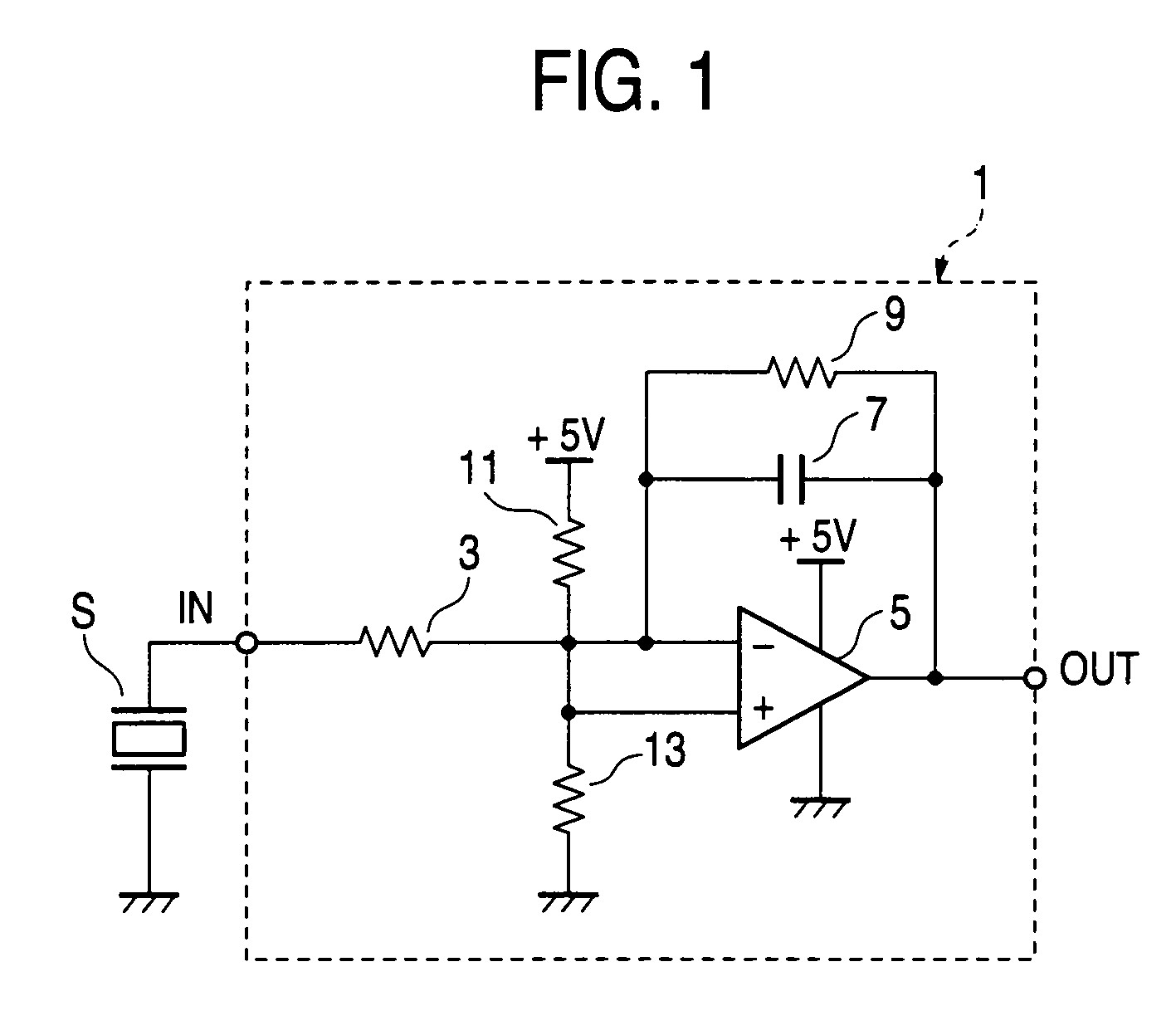
[0007]That is, in the charge amplifier according to the first configuration of the present invention, the operational amplifier has a plus side power source input terminal connected to a plus power source and a minus side power source input terminal grounded, so that the operational amplifier is supplied with a single power source. Further, an offset voltage lower than the plus power source voltage but higher than the ground potential is applied to the non-inverted input terminal of the operational amplifier. Accordingly, even in the case where only the single power source is supplied to the operational amplifier, the change of pressure in both positive and negative directions can be converted into a voltage signal with the offset voltage as its center. According to the charge amplifier configured thus, cost can be suppressed because a double power source is not required.
[0008]When here is the piezoelectric pressure sensor placed in such a bad environment that the piezoelectric pressure sensor is attached, for example, to an internal combustion engine of an automobile and used for detecting in-cylinder pressure, insulation resistance of the piezoelectric pressure sensor, that is, resistance between opposite ends of the piezoelectric pressure sensor may be reduced. In such a case, the output signal of the charge amplifier may cling to the power source voltage because of the influence of a leakage current generated by reduction in insulation resistance, so that the charge amplifier may malfunction.
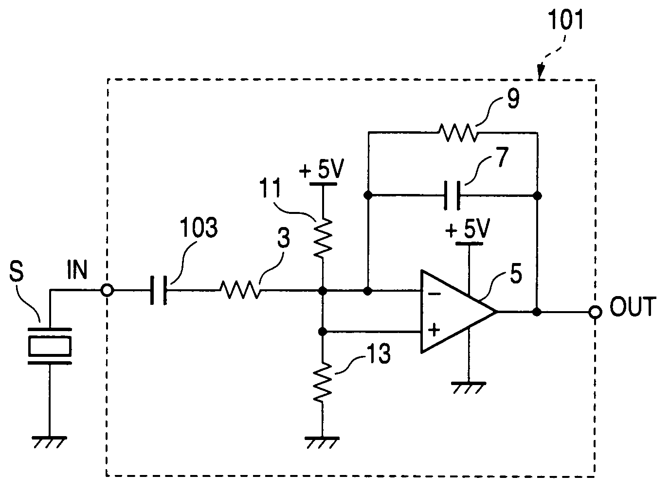
[0009]Therefore, according to a second configuration of the present invention, a coupling capacitor may be preferably provided between the inverted input terminal of the operational amplifier and the other terminal (the terminal opposite to the grounded terminal) of the piezoelectric pressure sensor. In this configuration, even in the case where insulation resistance of the piezoelectric pressure sensor is reduced, the output signal of the charge amplifier can be restrained from clinging to the power source voltage because of the influence of the leakage current.
[0012]In this configuration, the potential difference between the ground potential on the piezoelectric pressure sensor side and the ground potential on the charge amplifier side can be suppressed to improve the accuracy of the output signal of the charge amplifier.
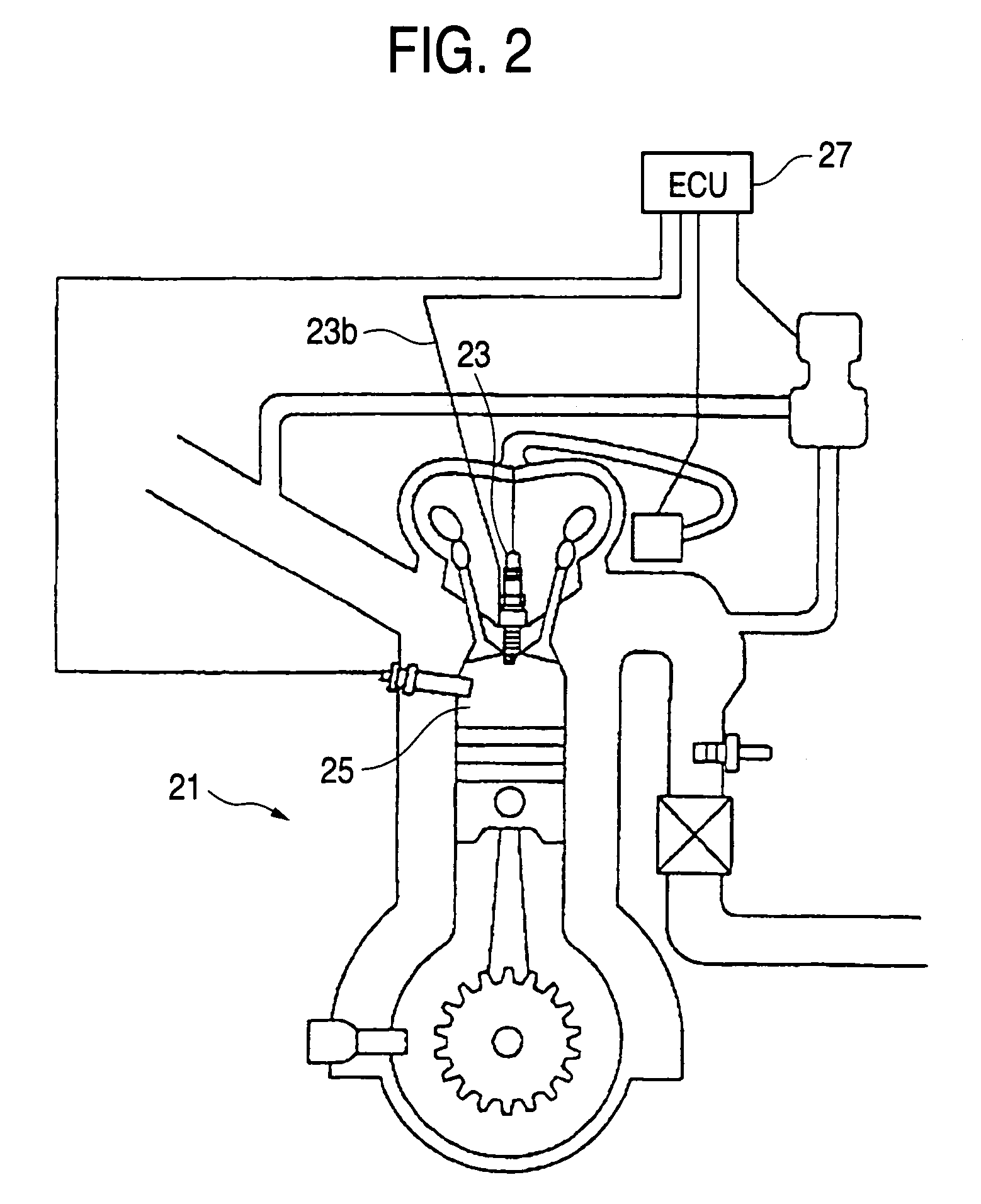
[0014]Incidentally, when the charge amplifier according to (any one of the first to fifth configurations of) the present invention is applied to a piezoelectric pressure sensor for detecting in-cylinder pressure of an internal combustion engine on the basis of change of clamping load of a spark plug detected by a piezoelectric element provided on a mount seat of the spark plug, a high effect is exhibited. That is, in an automobile, because electric power supply is generally performed from a battery of a plus power source, the charge amplifier according to the first configuration of the present invention is fit to use. Further, because such a piezoelectric pressure sensor is placed in such a bad environment that insulation resistance of the piezoelectric pressure sensor is apt to be reduced, the charge amplifier according to the second configuration of the present invention is fit to use.

Problems solved by technology

In such a case, the output signal of the charge amplifier may cling to the power source voltage because of the influence of a leakage current generated by reduction in insulation resistance, so that the charge amplifier may malfunction.

Method used


Image

  • Charge amplifier for piezoelectric pressure sensor
  • Charge amplifier for piezoelectric pressure sensor
  • Charge amplifier for piezoelectric pressure sensor

Examples


first embodiment

[0034]FIG. 1 shows a charge amplifier 1 as a first embodiment for converting combustion pressure in an internal combustion engine into an electric signal. Incidentally, the charge amplifier 1 is formed in the inside of an engine control unit (ECU) 27 which will be described later.

[0035]As shown in FIG. 1, one end of a piezoelectric pressure sensor S is grounded. An inverted input terminal of an operational amplifier 5 is connected to the other end of the piezoelectric pressure sensor S through an input terminal in of the charge amplifier 1 and a resistor 3. An FET is used as an input portion of the operational amplifier 5.

[0036]An output terminal of the operational amplifier 5 is connected to the inverted input terminal of the operational amplifier 5 through a feedback capacitor 7. A feedback resistor 9 is connected in parallel to the feedback capacitor 7. The feedback resistor 9 is provided for suppressing the temperature drift of a piezoelectric element.

[0037]A non-inverted input ...

second embodiment

[0046]Next, the present invention will be described.

[0047]FIG. 4 shows a charge amplifier 101 as a second embodiment. The charge amplifier 101 is configured 80 that a coupling capacitor 103 is provided between the inverted input terminal of the operational amplifier 5 and the piezoelectric pressure sensor S in addition to the charge amplifier 1 according to the first embodiment. That is, the coupling capacitor 103 is provided so as to be series-connected to the resistor 3 which is provided between the inverted input terminal of the operational amplifier 5 and the piezoelectric pressure sensor S. Incidentally, because this embodiment is the same as the charge amplifier 1 according to the first embodiment except the aforementioned point, description will be omitted.

[0048]Incidentally, when the piezoelectric pressure sensor S is placed in such a bad environment that the piezoelectric pressure sensor S is attached to the internal combustion engine 21 of the automobile and used for detec...


PUM

PropertyMeasurementUnit
voltageaaaaaaaaaa
capacitanceaaaaaaaaaa

Abstract

An object of the present invention is to provide a charge amplifier which can be operated at low cost so that electric charge generated in a piezoelectric pressure sensor having one end grounded is converted into a voltage signal.In the charge amplifier (1) according to an embodiment of the present invention, a plus side power source input terminal of an operational amplifier (5) is connected to a plus power source (+5 V) while a minus side power source input terminal of the operational amplifier (5) is grounded, so that the operational amplifier (5) is supplied with a single power source. Further, an offset voltage lower than the plus power source voltage but higher than the ground potential is applied to a non-inverted input terminal of the operational amplifier (5). Accordingly, change of pressure in both positive and negative directions can be converted into a voltage signal with the offset voltage as its center though the operational amplifier (5) is driven by a single power source. That is, cost can be suppressed because a double power source is not required.

Description

TECHNICAL FIELD[0001]The present invention relates to a charge amplifier by which electric charge generated in a piezoelectric pressure sensor having one grounded end is converted into a voltage signal.BACKGROUND ART[0002]A charge amplifier by which electric charge generated in a piezoelectric pressure sensor grounded to a mount target is converted into a voltage signal has been heretofore formed by use of an operational amplifier. Combustion pressure of an internal combustion engine, however, varies to both a positive value and a negative value. Therefore, there is employed a method in which the operational amplifier is operated by a double power source (having a pair of positive and negative power sources, for example, of ±5 V) to convert electric charge into a voltage signal.[0003]For example, a charge amplifier shown in FIG. 17 is one of this type charge amplifiers. In the charge amplifier 501, an inverted input terminal of an operational amplifier 505 is connected, through a re...

Claims


Application Information

Patent Timeline
Patent Type & Authority Patents(United States)
IPC IPC(8): H03F1/00H03F1/38H03F3/04F02P13/00G01L9/00G01L9/08G01L23/10
CPCG01L9/085G01L23/10
Inventor MATSUI, MASAYOSHIOKAZAKI, KOJI
Owner NGK SPARK PLUG CO LTD
Learn More