Smart recognition apparatus and method

a recognition apparatus and smart technology, applied in the field of smart recognition system, can solve the problems of mismatching an electrosurgical generator and the instrument, increasing patient risk, and affecting the safety of patients, so as to prevent misapplication of rf energy to the patient, reduce the risk of patient injury, and improve safety

Inactive Publication Date: 2006-05-16
COVIDIEN AG
View PDF15 Cites 501 Cited by
  • Summary
  • Abstract
  • Description
  • Claims
  • Application Information

AI Technical Summary

Benefits of technology

[0012]The preferred embodiment of the smart connector sensing approach has a non-contact, coded proximity detector that uses a diffuse surface, infrared reflective coupling. Delineation of this smart sense topology yields benefits providing the immunity referenced as an intrinsic property of the means used. A non contact technique avoids problems associated with mechanical alignment, component engagement and part mating orientation. Physical contact for sensing between mating components is not required for identity recognition. Coded proximity detection provides a unique identity association between plugged medical instruments and Rf energy sources. Multiple integrated optical paths, each containing both emitting and receiving components, proximally detect a unique Nth bit code identification for each medical instrument, plugged into an Rf energy source. Identification problems, associated with memory communication and data storage and registration and fatigue problems caused by component engagement alignment problems of multiple sensors for code identity, are avoided.
[0013]A light coupled, non-magnetic approach, avoids instrument identity problems with electromagnetic (EMI) interference. Light coupled identity sensing is immune to this noise. A light coupled technique, also avoids problems caused by electrical discontinuity, due to a mechanical disconnection of wire contacts between hardwire connections, or switches. A diffuse surface reflective coupling, avoids problems associated with optical axial alignment and focused optics. Unfocused optical components are preferred to proximally detect plugged instruments with diffuse surface reflection. Optimal smart sense recognition is obtained from non-planer, diffuse surface, including medical instrument plugs located within a proximal range from the smart sense components. As a result, tight optical and mechanical registration tolerances, along with high polished optical surfaces are not required to maximize instrument recognition and signal recovery.
[0015]The smart recognition system for electrosurgery provides an accurate medical instrument identification, for instruments attached to an electrosurgical generator source of high frequency electrosurgical energy. A control of the application of Rf energy during surgical procedures is also disclosed. Specific Rf power levels developed in the electrosurgical generator may be uniquely activated and coupled to individually recognized medical instruments for performing electrosurgery. Activation and surgical use of the Rf energy source are only allowed with an appropriate validation from the smart recognition system. This occurs when the proper medical instrument has been attached to the electrosurgical generator. Using this approach to control the power source for a particular tissue and to achieve the desired clinical effect prevents misapplication of Rf energy to the patient. As a result, the risk of patient injury is minimized and safety increased.

Problems solved by technology

Due to the variety of operative electrosurgical procedures requiring various levels of radio frequency energy delivery from an attached instrument, problems arise with mismatching an electrosurgical generator and the instrument.
The operating rooms with a variety of instruments and generators available for surgery create a potential for mismatch problems and thus may increase the patient risk.
A problem arises when the memory is located external to the power supply requiring hardwire connections.
The communicated data transmission from the memory to the control may have an error due to radiated emissions from radio frequency energy wires located closely when delivered by the electrosurgical generator during surgery.
Radio frequency exposure will interfere with the identification information being transmitted so it becomes difficult to determine that the correct medical instrument is attached to the power source.
In addition a further problem is presented because the memory means must be located in the reusable part of the medical instrument.
For purposes of instrument identification, this patent restricts application to reusable medical instruments and prohibits an instrument identification for low cost disposables.
A problem arises with this approach, as the integrity of the identity depends on the engagement with the mating of components.
A degradation of this identification occurs, with repeated engagements causing deterioration of the mating switch to contact interface between components.
A secondary problem also occurs from the multiple engagement process as this approach requires a specific orientation alignment between mating surfaces.
Repeated component engagements will also deteriorate this orientation alignment and thus degrade the accuracy in maintaining the identity.
Exposure of this system to radio frequency energy used in electrosurgery, could effect the integrity of the magnetic smart card and degrade the ability of the magnetic based card reader to accurately decode its proper identity.
Indeterminate magnetic sources present in the operating room also creates additional major problems for this system and would make its use in electrosurgery suspect.
The '062 patent is limited in use, in that, it provides for detection when a mating plug is either inserted or removed from the receptacle.
Numerous problems are presented by this system.
Second, the power applied to the receptacle cannot be differentiated between specific pluggable instruments.
Also, additional problems are presented, because a specific optical axial alignment is required for beam passage, through the openings in the power receptacle contacts, thereby requiring a specific mechanical alignment integrity.
Multiple identification problems exist with radio frequency based equipment due to radiation coupling with the electromagnetic conductive strip and antenna which will deteriorate the identity signals.
Error borne signals lose their identity and become inaccurate with decoding.
This will reduce the signal to noise ratio during information transfer and lower the accuracy of the identity information recovered.
A problem with this type of recognition system makes it error borne and unacceptable for code identification in radio frequency systems.
This will confuse the card reader antenna and detector electronics.
Erroneous signal components will be processed along with the identification signal; thus, generating errors in the detected signal.
The recognition system digital security code could not be a true representation of the signal information and thus identification is inaccurate for use with radio frequency based equipment.
Insertion and removal of an encoder requires assembly, thereby making the accuracy and repeatability of the identification process suspect and prone to error.
Recovery of the smart signal interface is dependent on the reliability of the electrical and mechanical connections required as mechanical misregistration and intermittent electrical contacts will degrade accuracy.
In applications where radio frequency energy exists proximate to the encoding, the corruption of electronic signals used for identity recognition will result.
Radio frequency energy will radiate and conductively couple with electronic or memory devices to reduce the accuracy of decoded signals.

Method used


Image

  • Smart recognition apparatus and method
  • Smart recognition apparatus and method
  • Smart recognition apparatus and method

Examples


Embodiment Construction

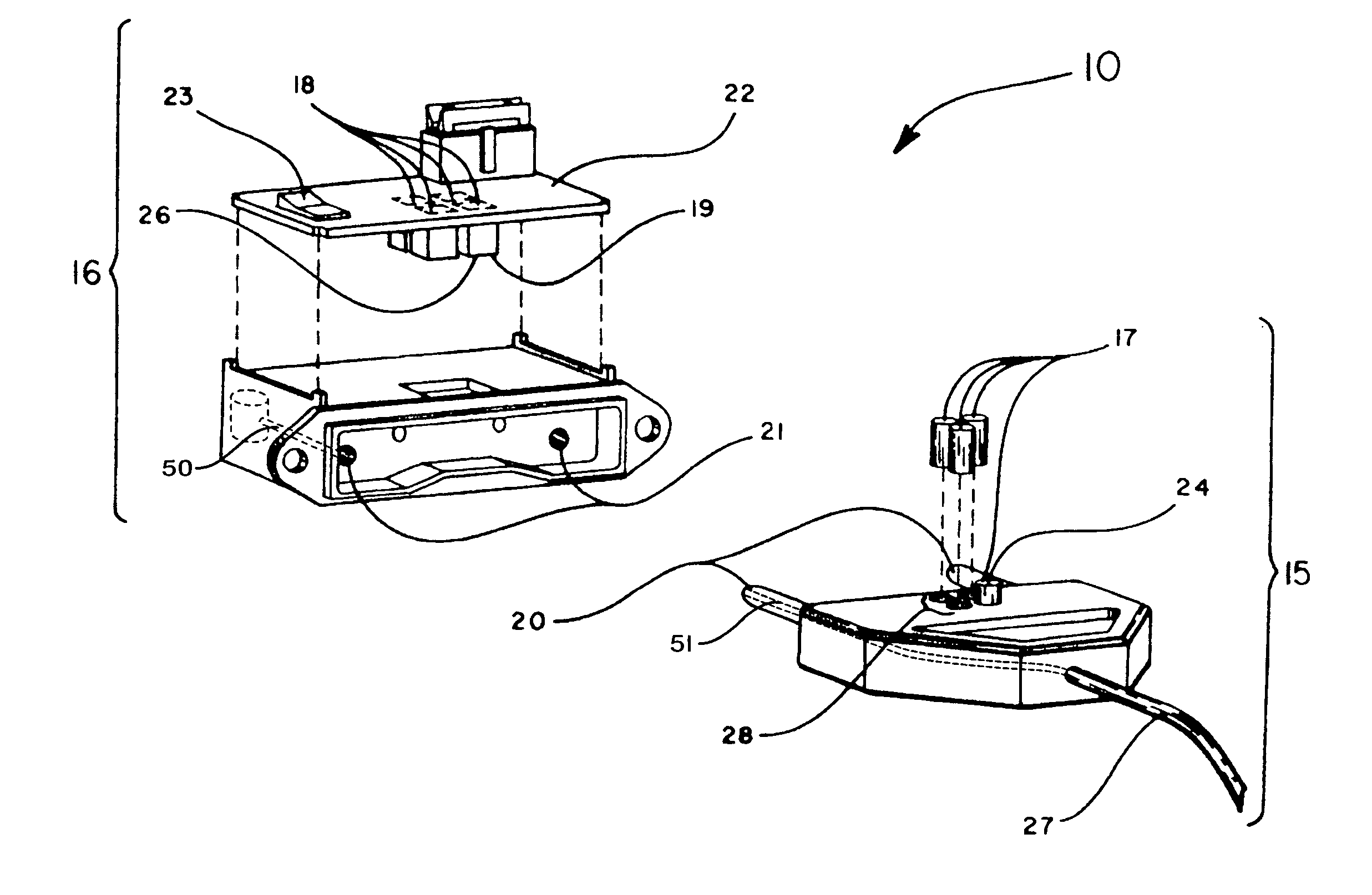
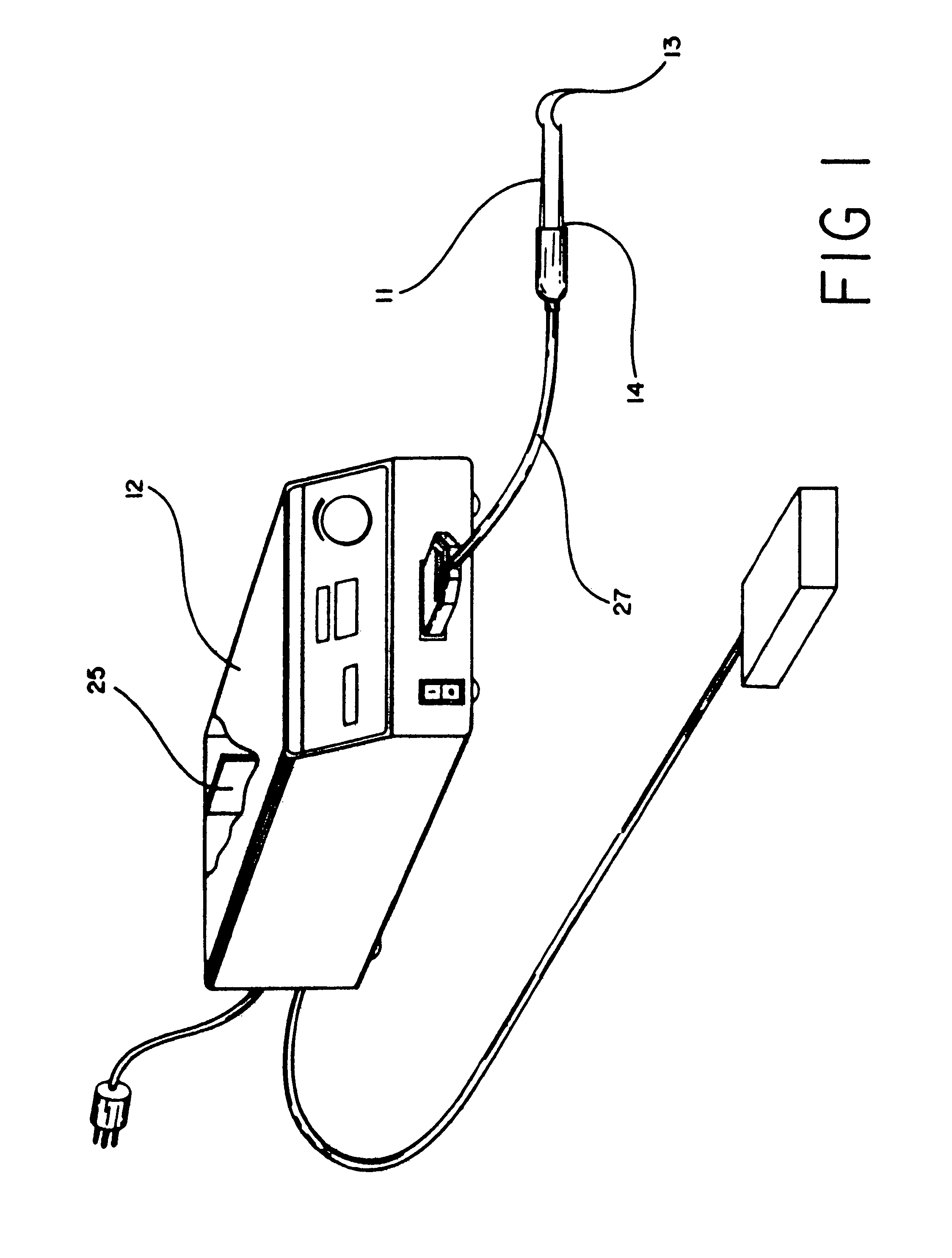
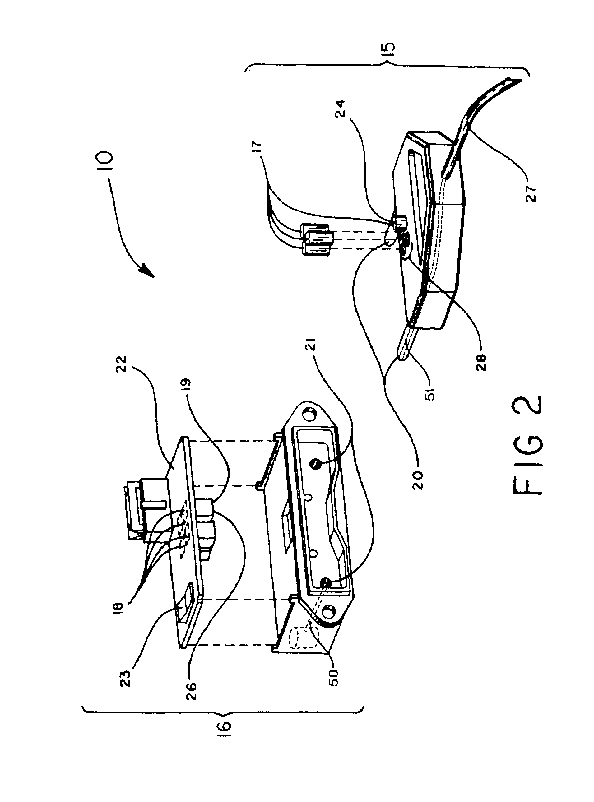
[0018]A qualifying connection 10 is disposed between an instrument 11 and a source of medical 12 treatment for passage of treatment energy from the source of medical treatment 12 through the qualifying connection 10 to the instrument 11 and to a patient. The qualifying connection 10 selectively permits passage of information from the instrument 11 to the source of medical treatment 12 in FIGS. 1 and 2. The qualifying connection 10 includes the instrument 11 having a distal end 13 for treatment of the patient and a proximal end 14 for manipulation by a surgeon. The instrument 11 is connected to the qualifying connection 10. The source of medical treatment 12 provides energy delivery to the instrument 11. The source of medical treatment 12 is attached to the qualifying connection 10. A first part 15 of the qualifying connection 10 connects to the instrument 11 in FIG. 2. A second part 16 of the qualifying connection 10 is carried on and connected to the source of medical treatment 12....


PUM


Abstract

A qualifying connection for an instrument attaches to a source of electrosurgery energy and to the instrument and has first and second parts coupled to the instrument and the source, respectively. Optical couplings on the connection transmit invisible energy to identify the instrument and are proximate on the first and second parts. A light modifier on the first part is proximal to the second part for modification of radiation in the infrared wavelengths so infrared transmitters encode signals and non-contact coded proximity detectors on the second part are the coupled detectors. Mechanical attachments include conjugating male and female portions which physically extend between the parts and matingly engage. An identifying circuit couples to the second part and responds to invisible light optically communicated across the couplings for verifying the type of instrument connected by the cable to the source. A method of using the connection has steps including juxtaposing and conjugating the parts with attachments and couplings for transmitting invisible optical energy to identify the instrument. The method includes modifying the invisible optical energy with geographically disposed proximate couplings of the parts when the attachments engage and the couplings are proximate. Passing and assessing signals of the modified energy are transmitted through the connection and to an identifying circuit in the source.

Description

CROSS REFERENCE TO RELATED APPLICATIONS[0001]This application is a continuation of U.S. application Ser. No. 10 / 166,500 filed on Jun. 10, 2002 now U.S. Pat. No. 6,685,701 by Orszulak et al. entitled “SMART RECOGNITION APPARATUS AND METHOD” which is a continuation of U.S. application Ser. No. 09 / 528,380 filed on Mar. 17, 2000 now U.S. Pat. No. 6,402,743 by Orszulak et al. entitled “SMART RECOGNITION APPARATUS AND METHOD” which is a continuation of U.S. patent application Ser. No. 08 / 988,362 filed on Dec. 10,1997 now U.S. Pat. No. 6,068,627 by Orszulak et al. entitled “SMART RECOGNITION APPARATUS AND METHOD”, the entire contents of all of these applications are incorporated by reference herein.FIELD OF THE INVENTION[0002]This relates to a smart recognition system for electrosurgery and a qualifying connection with non contact, coded proximity detection, using diffuse surface, infrared reflective coupling as an instrument identification process. More particularly, the system identifies...

Claims


Application Information

Patent Timeline
Patent Type & Authority Patents(United States)
IPC IPC(8): A61B18/04A61B17/00A61B18/00A61B18/12A61B18/14A61B18/18A61B19/00A61M1/00G02B6/38G02B6/42H04B10/00H04B10/077H04B10/116H04B10/80
CPCA61B18/12A61B18/14A61B19/44G02B6/3895A61B18/18A61B2017/00482G02B2006/4297A61B2018/00988A61B2019/448A61B2217/005A61B2217/007A61B2018/00178A61B90/90A61B90/98
Inventor ORSZULAK, JAMES HENRYDOBBINS, JR., GARY LEE
Owner COVIDIEN AG
Why Eureka
Try Eureka