Fuel injection system

a fuel injection system and fuel injection timing technology, applied in the direction of fuel injection pumps, machines/engines, electric control, etc., can solve the problems of high stress limited injection pressure and injection timing, and high pressure within the pump and the rail, so as to reduce pollutant emissions and noise, improve efficiency, and reduce the effect of pollutant emissions

Inactive Publication Date: 2006-05-23
DELPHI INT OPERATIONS LUXEMBOURG S A R L
View PDF41 Cites 15 Cited by
  • Summary
  • Abstract
  • Description
  • Claims
  • Application Information

AI Technical Summary

Benefits of technology

[0011]One advantage of the invention is the ability to control the injection of fuel at different pressure levels, without the need to relieve high pressure fuel to low pressure. The system therefore has improved efficiency over known common rail fuel systems. The accumulator volume may be charged with fuel at a moderate pressure of, say, 300 bar, and the pump means may be arranged to increase rail pressure further to, say, between 2000 and 2500 bar. Within one engine cycle it is therefore possible to vary the pressure of the injected fuel (and thereby the injection rate), and this has important implications for emissions levels. For example, it has been found that a two-stage injection including a pilot injection of fuel at a first, moderate pressure level followed by a main injection of fuel at a second, higher pressure level can help to reduce pollutant emissions and noise. This can be achieved relatively easily and efficiently using the fuel system of the present invention.
[0012]It is a particular benefit of being able to inject at two pressure levels, that a sequence of a main injection of fuel having the second (higher) pressure level followed by a post injection of fuel having the first (moderate) pressure level can be achieved and this can have benefits for after-treatment purposes.

Problems solved by technology

Although the use of a nozzle control valve in an Electronic Unit Injector provides a capability for controlling the injection timing, and such units are capable of achieving high injection pressures, both injection pressure and injection timing are limited to some extent by the nature of the associated cam drive.
However, achieving very high injection pressure within a common rail system is problematic and the high levels to which fuel must be pressurised can cause high stresses within the pump and within the rail.
The rail must therefore be pr

Method used


Image

  • Fuel injection system
  • Fuel injection system
  • Fuel injection system

Examples


Embodiment Construction

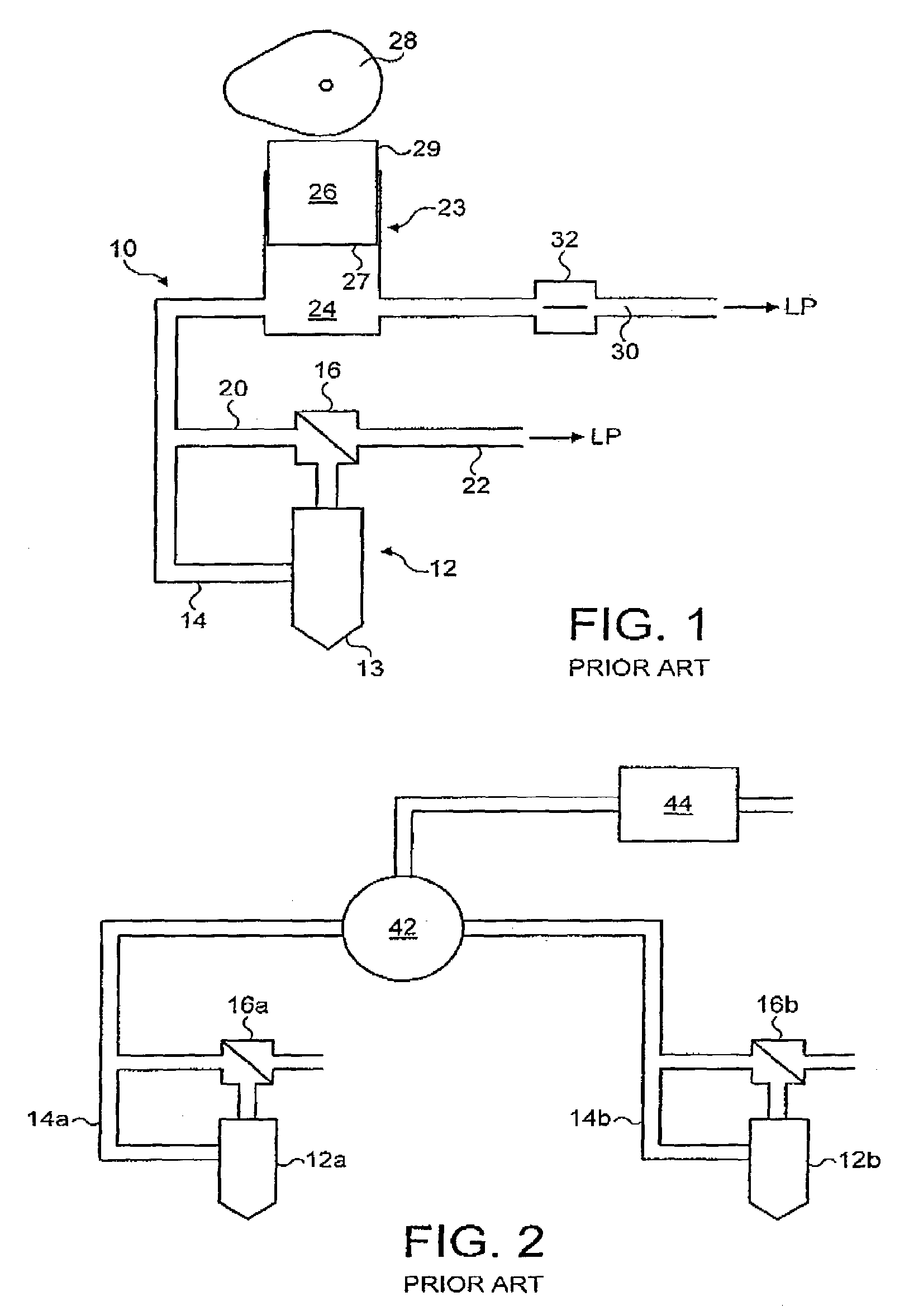
[0085]By way of background to the present invention, FIGS. 1 and 2 show known Electronic Unit Injector (EUI) and common rail fuel systems respectively. Referring to FIG. 1, a known EUI arrangement 10 includes an injector 12 and a high pressure fuel line 14 for providing a supply of fuel at high pressure to an injection nozzle 13 of the injector 12. A control valve means, typically in the form of a nozzle control valve 16 (alternatively referred to as a needle control valve), is arranged to control movement of a fuel injector valve needle (not shown) so as to control the delivery of fuel from the injection nozzle 13. The valve needle is engageable with a valve needle seating and movement of the valve needle away from the seating permits fuel to flow through one or more outlets of the injection nozzle 13 into the associated engine cylinder or other combustion space.

[0086]The nozzle control valve 16 is arranged within a further passage 20 in communication with the supply line 14 to con...


PUM


Abstract

A fuel injection system for supplying pressurized fuel to a fuel injector, the fuel injection system comprising an accumulator volume for supplying fuel at a first injectable pressure level to the fuel injector through a fuel supply passage, a pump arrangement for increasing the pressure of fuel supplied to the injector to a second injectable pressure level, and a valve arrangement operable between a first position in which fuel at the first injectable pressure level is supplied to the injector and a second position in which communication between the injector and the accumulator volume is broken so as to permit fuel at the second injectable pressure to be supplied to the injector. The injection system may include a valve arrangement in the form of a three-position valve or may include a shut off valve for controlling the supply of fuel through the fuel supply passage.

Description

FIELD OF THE INVENTION[0001]The present invention relates to a fuel injection system for an internal combustion engine, and in particular to a fuel injection system including an accumulator volume in the form of a common rail. The fuel system of the present invention is capable of providing a range of injection pressure and injection-rate shaping characteristics. The invention also relates to a common rail fuel system including a shut off valve, and to a shut off valve for use in a fuel injection system.BACKGROUND OF THE INVENTION[0002]In known fuel injector designs, a nozzle control valve is provided to control movement of a fuel injector valve needle relative to a seating and, thus, to control the delivery of fuel from the injector. A so-called Electronic Unit Injector (EUI) is an example of such an injector. An Electronic Unit Injector includes a dedicated pump having a cam-driven plunger for raising fuel pressure within a pump chamber, and an injection nozzle through which fuel ...

Claims


Application Information

Patent Timeline
IPC IPC(8): F02M1/00F02M47/02F02M57/02F02D41/40F02M45/00F02M45/02F02M45/04F02M45/06F02M47/00F02M51/00F02M59/10F02M59/16F02M59/36F02M59/46F02M63/00F02M63/02
CPCF02M45/02F02M45/04F02M45/063F02M47/02F02M47/027F02M57/023F02M59/462F02M63/0005F02M63/0007F02M63/0029F02M63/0045F02M59/102F02M2200/40
Inventor DRAPER, DAVID E.HARCOMBE, ANTHONY T.KNIGHT, ANDREW R.PANESAR, LUKHBIR S.
Owner DELPHI INT OPERATIONS LUXEMBOURG S A R L
Why Eureka
Try Eureka