Fluorescence observing apparatus

a fluorescence observing and apparatus technology, applied in lighting and heating apparatus, instruments, optical elements, etc., can solve the problem of limited film deposition to about 50 layers, and achieve the effect of efficient removal

Inactive Publication Date: 2006-05-23
OLYMPUS CORP
View PDF4 Cites 22 Cited by
  • Summary
  • Abstract
  • Description
  • Claims
  • Application Information

AI Technical Summary

Benefits of technology

[0012]The present invention is designed to use filters such that variations in the half-value wavelengths of the excitation filter unit and the absorption filter unit where humidity is changed from 10% to 95% are within 0.5 nm, and thereby Reason (1) is eliminated. Film forming techniques involve the use of ion assist processes, ion plating processes, and sputtering processes which are much higher in film density than the conventional vacuum evaporation methods. Consequently, even when the space between the half-value wavelength on the long-wavelength side of the excitation filter unit and the half-value wavelength on the short-wavelength side of the absorption filter unit is as narrow as 6–12 nm, the spectral characteristic curves of the filters are little shifted, and thus the transmission areas of the two filters do not over-lap. Since the space is made narrower than in the conventional practice, faint fluorescent light can be efficiently observed.
[0018]According to the present invention, in the fluorescence observing apparatus using the excitation filter unit and the absorption filter unit, faint fluorescent light can be efficiently taken out. Hence, when a living specimen is especially fluorescence-observed, it is possible to observe the specimen in vivo without deteriorating the specimen.

Problems solved by technology

In the vacuum evaporation method which has been used from the past, however, the problems of a fabrication error and intimate film deposition are produced and hence, in fact, film deposition is limited to about 50 layers.

Method used


Image

  • Fluorescence observing apparatus
  • Fluorescence observing apparatus
  • Fluorescence observing apparatus

Examples


first embodiment

[0027]In this embodiment, the present invention is applied to a microscope in which fluorescence observation can be carried out.

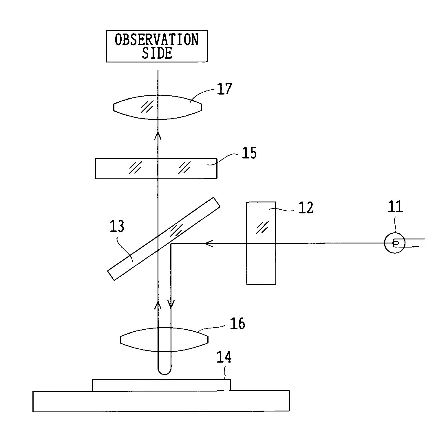
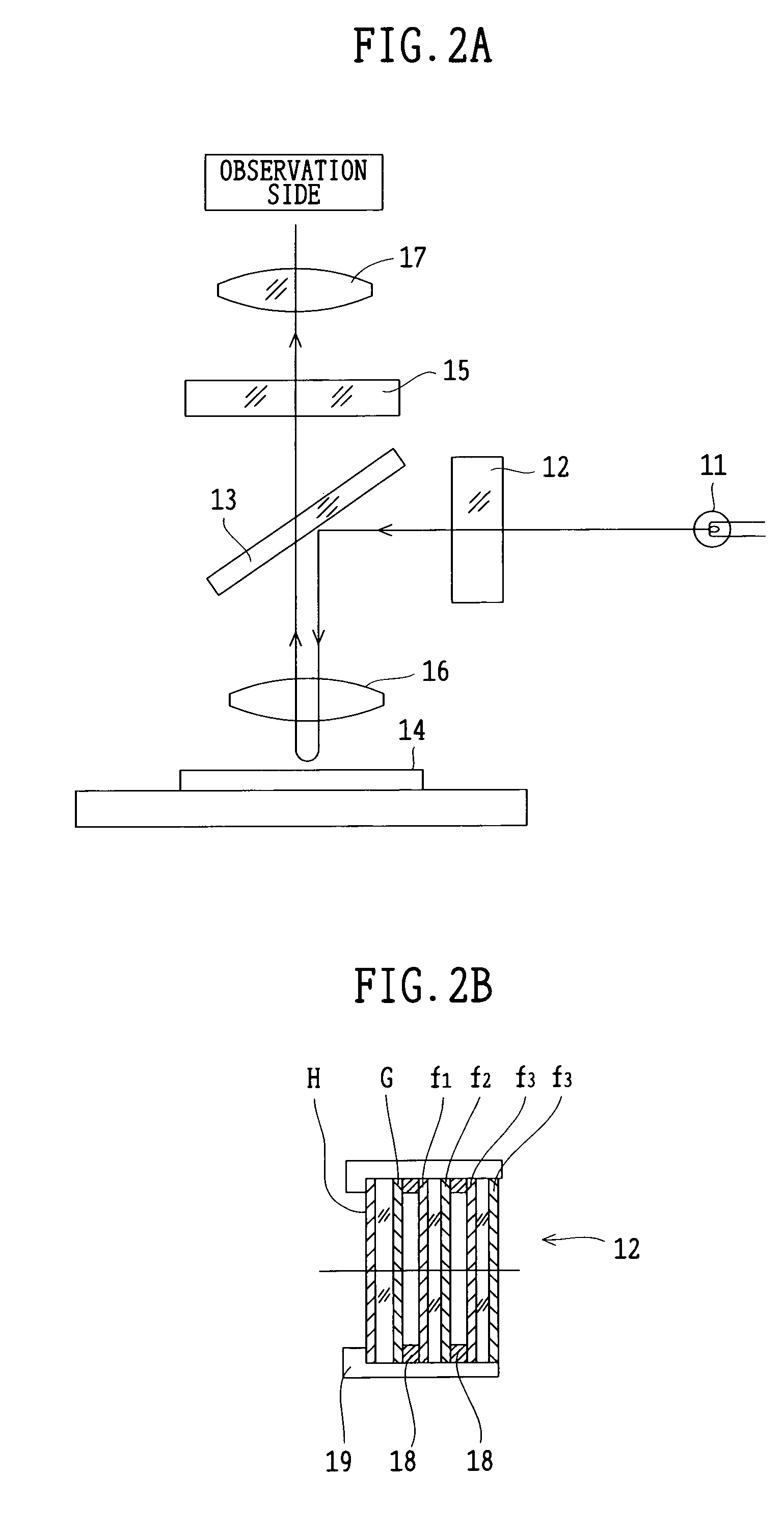
[0028]FIG. 2A shows the optical path of the microscope. Of light emitted from a light source 11, only light with particular wavelengths is selectively transmitted by an excitation filter unit 12. The light transmitted through the excitation filter unit 12 is such that its optical path is bent by a dichroic mirror 13, and a specimen 14 is irradiated with the light. By this irradiation, fluorescent light is produced from the specimen 14. Only the fluorescent light produced from the specimen 14 is selectively transmitted by an absorption filter unit 15. This fluorescent light, after being transmitted through an eyepiece 17, is observed on the observation side.

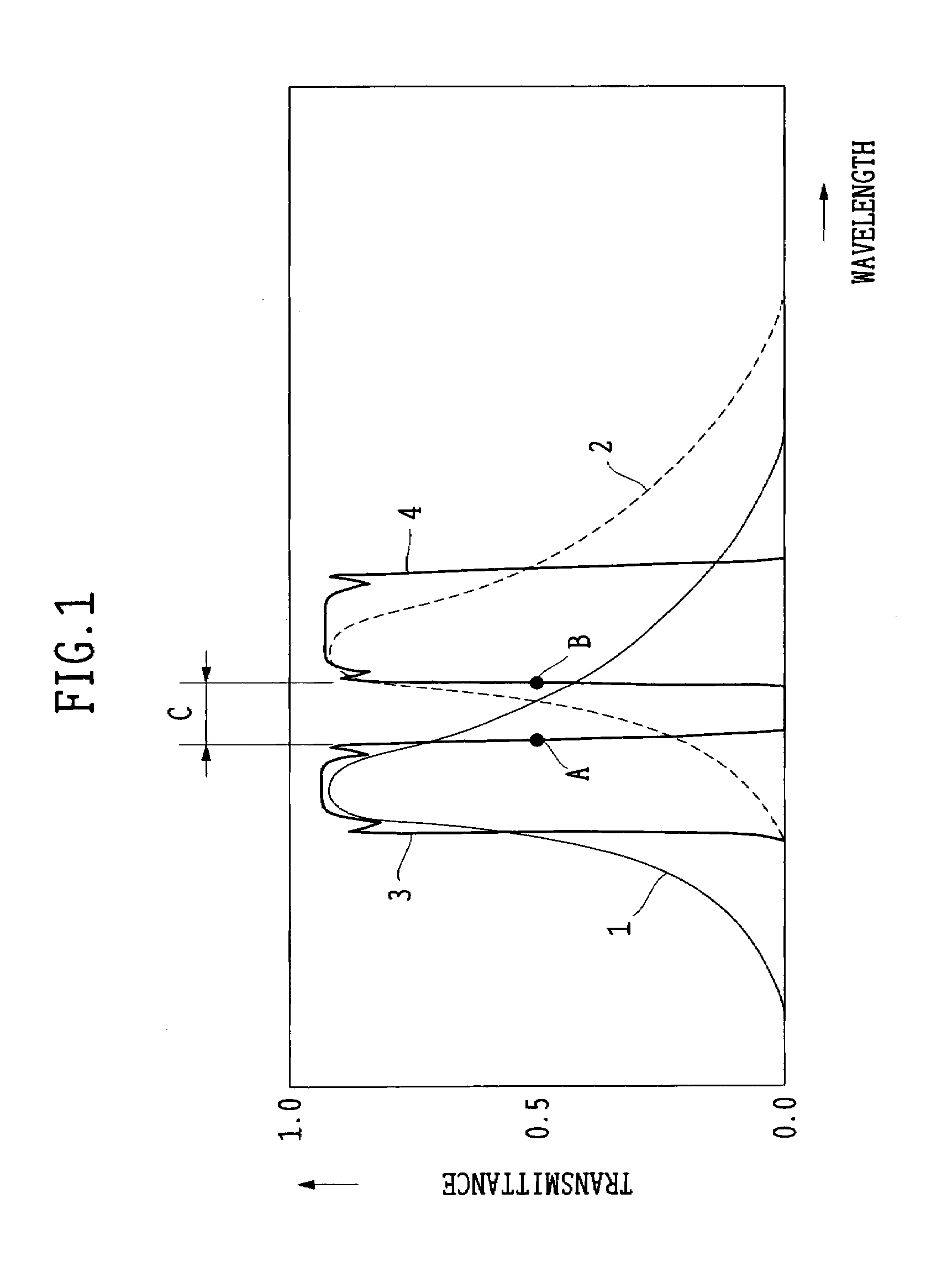
[0029]FIG. 3 shows spectral characteristic curves of the excitation filter unit 12, the dichroic mirror 13, and the absorption filter unit 15, used in the microscope. In this figure, reference symbol D de...

second embodiment

[0041]In this embodiment, the present invention is applied to a medical endoscope in which the disease of the living tissue is diagnosed by making the fluorescence observation.

[0042]A description is given of the medical endoscope. As shown in FIG. 5, a medical endoscope 20 roughly includes an endoscope body 22 provided with an inserting section 21 inserted into the human body, a light source section 23, and an imaging section 24. A monitor TV 26 is connected to the imaging section 24 through a video switching device 25.

[0043]In the light source section 23, a light source 30 for illuminating a living body 35 in the human body and an excitation filter unit 31 used for the fluorescence observation are arranged. When the fluorescence observation is not made, the excitation filter unit 31 is moved outside the optical path of a light beam for illumination emitted from the light source 30. A light guide fiber 33 which introduces illuminating light into the human body is encased in a connec...


PUM


Abstract

A fluorescence observing apparatus has an excitation filter unit for transmitting only exciting light with particular wavelengths, of illuminating light, and an absorption filter unit for transmitting only fluorescent light produced from a specimen by irradiating the specimen with the exciting light to block the exciting light. In this case, the space between the half-value wavelength on the long-wavelength side of the excitation filter unit and the half-value wavelength on the short-wavelength side of the absorption filter unit is in the range of 6–12 nm, and variations in the half-value wavelengths of the excitation filter unit and the absorption filter unit where humidity is changed from 10% to 95% are within 0.5 nm. Whereby, faint fluorescent light is efficiently taken out and the observation can be made.

Description

BACKGROUND OF THE INVENTION[0001]1. Field of the Invention[0002]This invention relates to a fluorescence observing apparatus used in a microscope or an endoscope.[0003]2. Description of Related Art[0004]It has been carried out that a specimen, such as living tissue, is irradiated with exciting light and thereby fluorescent light produced from the specimen is used for observation. This fluorescence observation requires the use of an excitation filter unit for transmitting only exciting light with particular wavelengths, of illuminating light, and an absorption filter unit for transmitting only fluorescent light produced from the specimen by irradiating the specimen with the exciting light to block the exciting light.[0005]For example, an endoscope for fluorescence observation is set forth in Japanese Patent Kokai No. Hei 10-239517. This fluorescence observing endoscope apparatus is designed to carry out the fluorescence observation in such a way that the excitation filter unit transm...

Claims


Application Information

Patent Timeline
Patent Type & Authority Patents(United States)
IPC IPC(8): F21V9/04F21V9/06G02B21/16
CPCG02B21/16
Inventor KAWAMATA, KENWADA, YORIOTOYOHARA, NOBUYOSHIDEGUCHI, TAKESHIUZAWA, KUNIHIKOSAKAMOTO, JOJI
Owner OLYMPUS CORP
Why Eureka
Try Eureka