Controlled ESR low inductance multilayer ceramic capacitor

a multi-layer ceramic capacitor and low inductance technology, applied in the direction of fixed capacitors, stacked capacitors, fixed capacitor details, etc., can solve the problems of unintended logic gate switching, no of the above approaches allows for an increase in the esr of the capacitor, and none of the previous approaches may function effectively during the operation of the device, so as to achieve less surface area

Inactive Publication Date: 2006-05-30
KYOCERA AVX COMPONENTS CORP
View PDF31 Cites 71 Cited by
  • Summary
  • Abstract
  • Description
  • Claims
  • Application Information

AI Technical Summary

Benefits of technology

[0026]The completed capacitor body comprises a plurality of first electrode elements and a plurality of second electrode elements interleaved to form a stack wherein each of the first electrode elements opposes one of the at least one second electrode elements. Each of such pluralities of first and second electrode elements is formed in a shape other than a flat plate so as to increase the length of the path of the electricity flow. Several alternative shapes may be used including a spiral, a mesh or a serpentine pattern that enhances the capacitor's equivalent series resistance (ESR) by providing a longer current path throughout the device.
[0034]In an alternative to the above exemplary embodiment, the tab structures that connect the internal electrode elements to their respective terminations could instead be formed with a resistive material as opposed to traditional conductive materials similar to the electrode elements themselves. By printing the electrode tabs with resistive material, another embodiment of the present technology with controlled ESR is provided. In still another alternative to the above exemplary embodiment, the tab structures could be narrowed providing less surface area over which the electricity could flow thus increasing its ESR to a predetermined value.

Problems solved by technology

The need for such capacitors is due to the unintended generation of power supply noise (i.e., voltage fluctuations) across the power supply buses, a result of the simultaneous switching of logic gates during current flow.
Such voltage fluctuations may have the undesirable result of causing unintended logic gate switching.
While useful for their purpose, neither of the above approaches allows for an increase in the ESR of a capacitor while maintaining low inductance and the effective capacitance of the device.
Still further, none of the previous approaches may function effectively during operation of the device at the higher frequencies required by today's electronics.
Today's systems use many capacitors in parallel, therefore, combined resistance (impedance) in the circuits is extremely low, especially at the circuits resonant frequency.
This phenomenon creates unwanted electrical noise in the circuit and can lead to an undesirably excessive emission of radio frequency (RF) signals.
While various aspects and alternative features are known in the field of multilayered capacitors and other specialized electronic devices, no one design has emerged that generally addresses all of the issues as discussed herein.

Method used


Image

  • Controlled ESR low inductance multilayer ceramic capacitor
  • Controlled ESR low inductance multilayer ceramic capacitor
  • Controlled ESR low inductance multilayer ceramic capacitor

Examples


Embodiment Construction

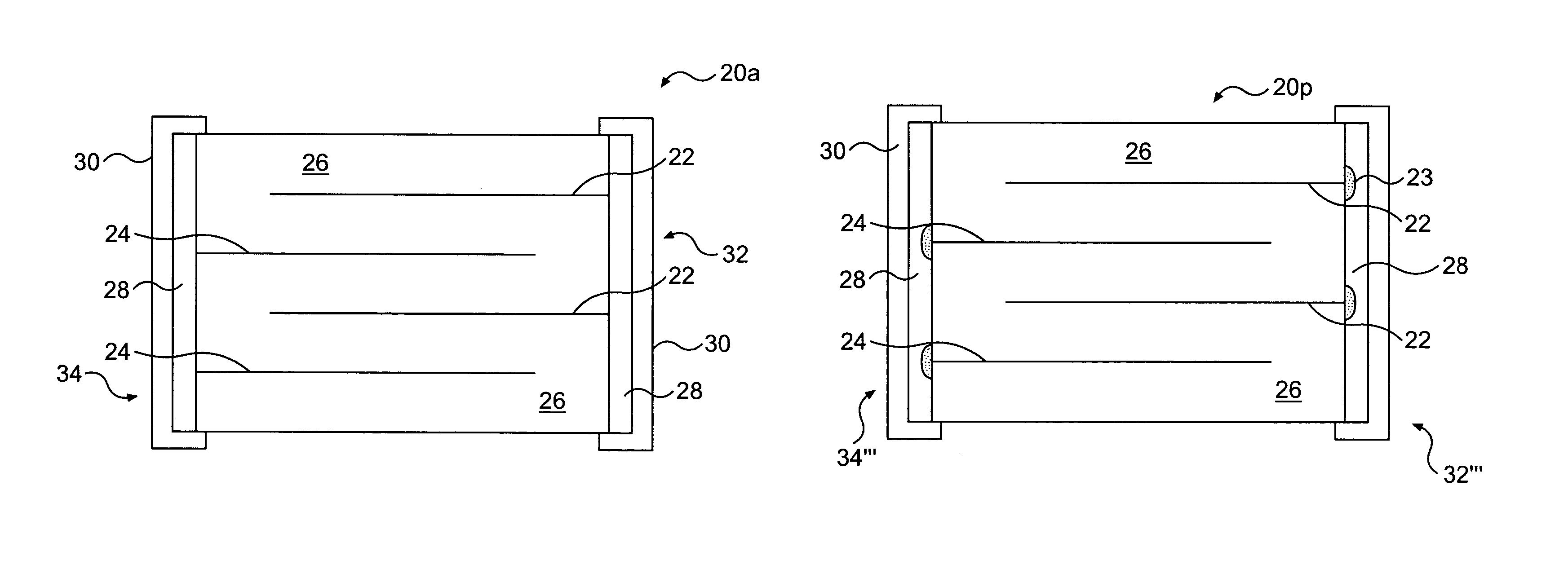
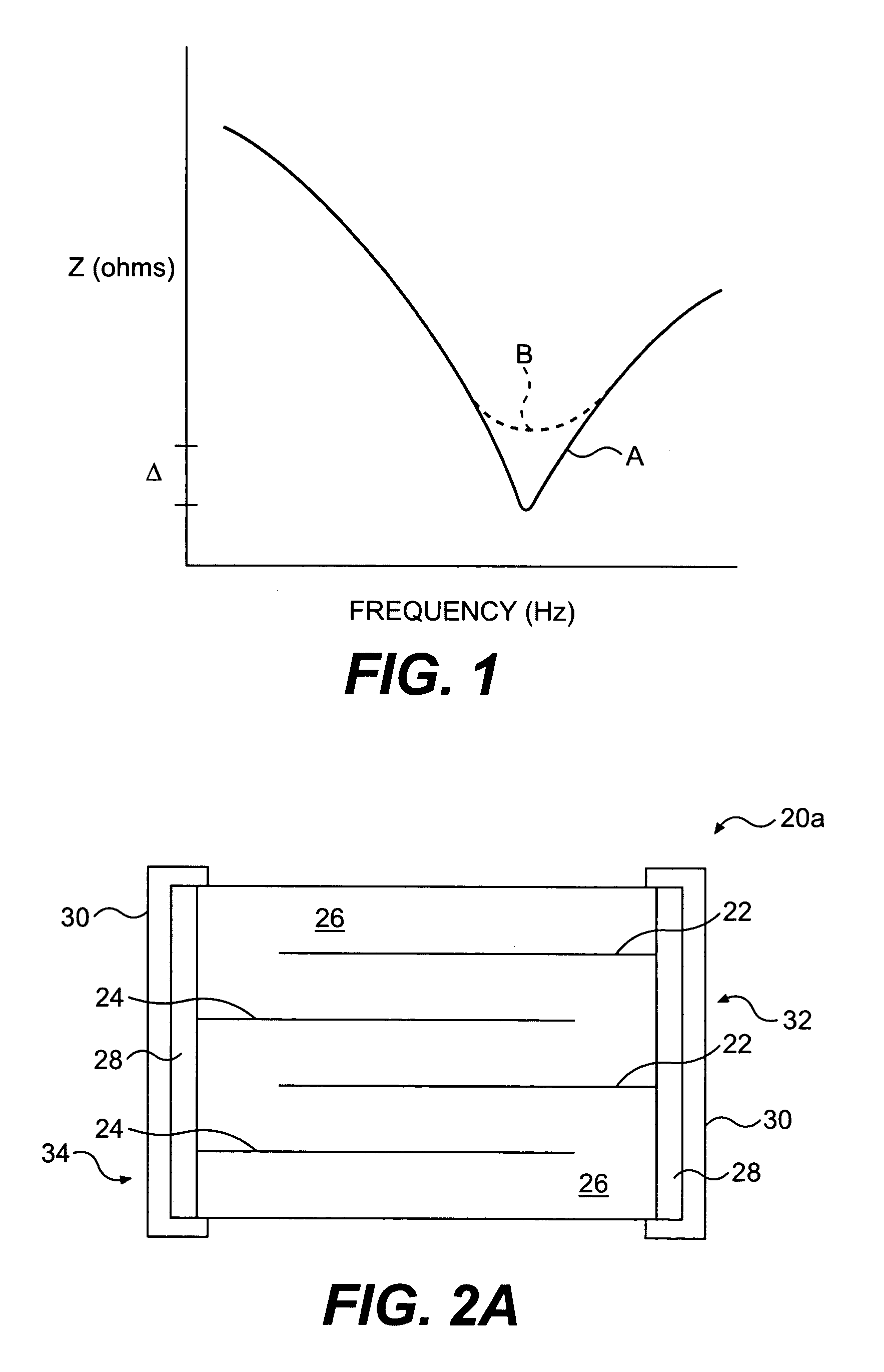
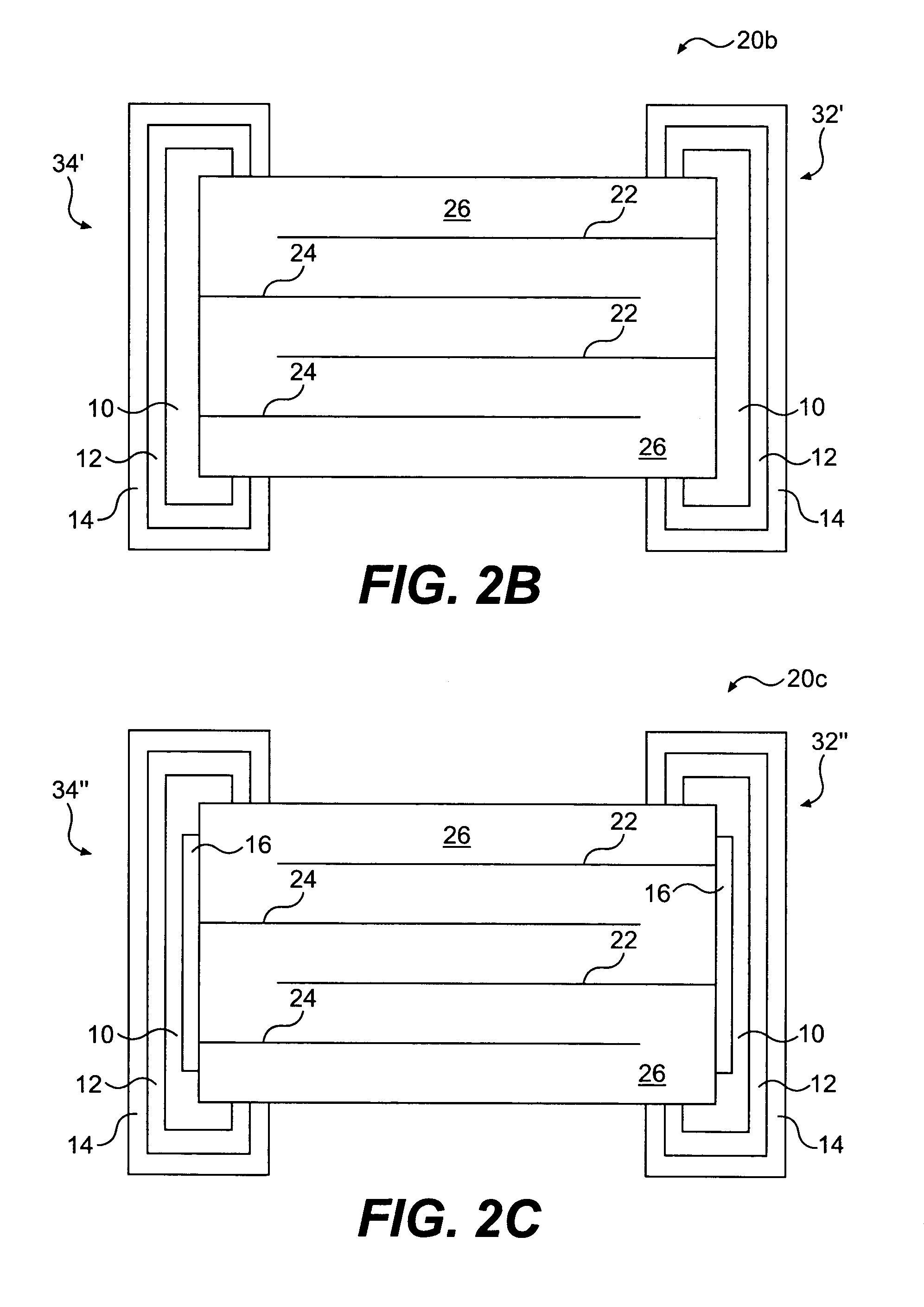
[0061]Reference will now be made in detail to presently preferred embodiments of the present technology, examples of which are fully represented in the accompanying drawings. Such examples are provided by way of an explanation of the technology, not limitation thereof. In fact, it will be apparent to those skilled in the art that various modifications and variations can be made in the present subject matter, without departing from the spirit and scope thereof. For instance, features illustrated or described as part of one embodiment can be used on another embodiment to yield a still further embodiment. Still further variations in selection of materials and / or characteristics may be practiced, to satisfy particular desired user criteria. Thus, it is intended that the present subject matter covers such modifications and variations as come within the scope of the present features and their equivalents.

[0062]As disclosed above, the present subject matter is particularly concerned with m...


PUM


Abstract

A multilayer ceramic capacitor assembly capable of exhibiting low high-frequency inductance and a controlled equivalent series resistance (ESR) while maintaining a useful capacitance value includes respective pluralities of first and second electrode elements interleaved to form a stack. Controlled ESR is achieved either through inclusion of specific types of materials or through alteration of the shape of various component parts. A resistive material may be used in typical end terminations, via terminations, electrode elements or connective tab structures. Additionally, the dielectric may be made lossy so as to enhance resistivity without overly affecting device capacitance. Still further, an additional layer of resistive material may be added to an outer device surface to connect filled-via terminations to end terminations or radial resistive prints may be used to only partially fill the vias. Finally, various electrode element configurations, such as flat plate, serpentine, mesh, L-, O- or U-shaped patterns, may be employed.

Description

PRIORITY CLAIMS[0001]This application claims the benefit of U.S. Provisional Application No. 60 / 386,617, entitled “CONTROLLED ESR LOW INDUCTANCE MULTILAYER CERAMIC CAPACITOR”, filed Jun. 6, 2002 and which is incorporated herein by reference for all purposes.BACKGROUND OF THE INVENTION[0002]The present subject matter generally relates to a capacitor assembly. More particularly, the present subject matter relates to a multilayer ceramic capacitor assembly for enhanced high frequency performance. Most particularly, the present subject matter relates to a multilayer ceramic capacitor assembly capable of exhibiting lower high-frequency inductance and a controlled equivalent series resistance (ESR).[0003]The development of higher speed microprocessor chips and the miniaturization of both the power conversion circuitry used to power those chips and the circuitry they drive have led to an increase in the demand for small footprint, low inductance capacitors that have a useful ESR value whil...

Claims


Application Information

Patent Timeline
Patent Type & Authority Patents(United States)
IPC IPC(8): H01G4/228H01G4/20H01G4/12H01G4/232H01G4/30
CPCH01G4/30H01G4/2325
Inventor RITTER, ANDREW P.GALVAGNI, JOHN L.
Owner KYOCERA AVX COMPONENTS CORP
Why Eureka
Try Eureka