
Self-propelled instrumented deep drilling system

a self-propelled, deep-drilling technology, applied in the direction of drilling pipes, drilling holes/well accessories, slitting machines, etc., can solve the problems of large volume, large disadvantages of the prior art, and conventional drill platforms that require a great deal of mass and packaging volume to accomplish the task of drilling, etc., to achieve energy self-sufficient, small, and robust in mobility

Inactive Publication Date: 2006-06-06
HONEYBEE ROBOTICS
View PDF15 Cites 46 Cited by
  • Summary
  • Abstract
  • Description
  • Claims
  • Application Information

AI Technical Summary

Benefits of technology

[0007]It is therefore a principal object of the present invention to provide an autonomous subsurface drilling device that eliminates the problems posed by tethers or umbilical tubes used for passage of cuttings. It is a particular object of the invention that the autonomous deep drilling device requires only modest support hardware, and that it is configured to be small, robust in mobility, and energy self-sufficient.
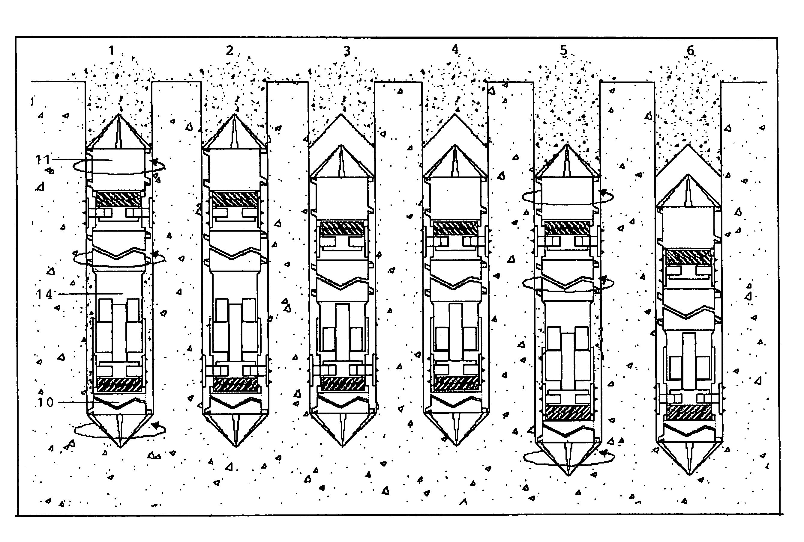
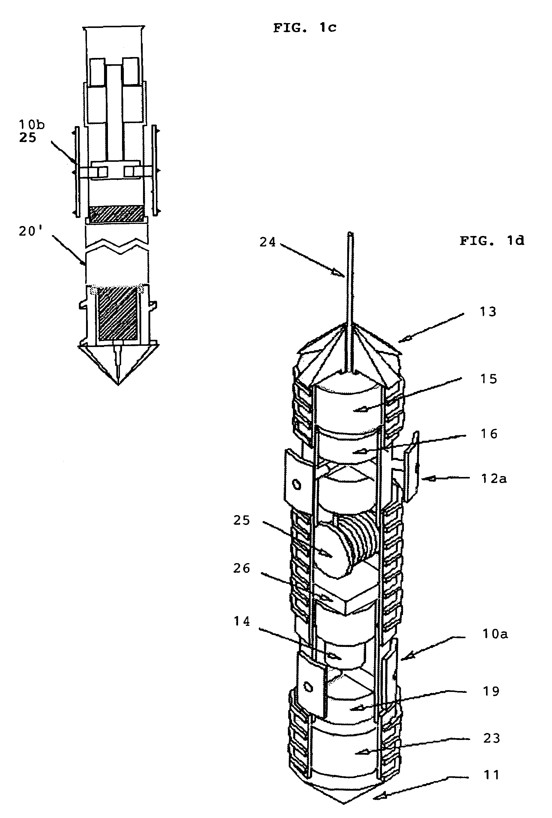
[0010]In another preferred embodiment, a front drill section has a drill head for cutting into the borehole and conveying cuttings through a center spine tube along the main axis of the device to an on-board depository for collecting the cuttings, so that cuttings do not have to be passed to the surface while the device is in operation deep below the surface. The feet sections of the device employ a foot scroll drive unit which spins about the longitudinal axis of the device in order to extend and provide radial thrust to the feet for gripping the borehole wall as well as providing coaxial alignment of the mechanism to the borehole. The axial thrust mechanism has a tandem set of thrusters in which the second thruster is used to provide the thrust needed for drilling, but not walking. The drilling thruster allows both feet sections to be locked onto the borehole wall while the drilling thruster is extended. Further, the forward feet section is placed as close to the drill head as possible so that a high level of drilling stiffness is insured.

Problems solved by technology

This approach requires a substantial amount of mass and volume as well as power to perform deep drilling with a long string of drill tubes into the ground.
The disadvantages of the prior art are many.
The conventional drill platform requires a great deal of mass and packaging volume to accomplish its task.
Typically, there is a degree of assembly or deployment involved as well as manpower to perform the drilling operations that adds to the overall complexity and therefore risk.
This type of massive, high power, complex machinery and associated flushing system would be totally unacceptable for use as probes that have to be flown and landed on any extraterrestrial bodies.
Moreover, the massive amounts of material that would have to be left behind would be a waste of resources and might contaminate the alien surroundings, thus compromising scientific objectives.
However, tether management for a subsurface probe that travels to depths below a kilometer may be an insurmountable engineering problem, especially in a planetary exploration setting.

Method used


Image

  • Self-propelled instrumented deep drilling system
  • Self-propelled instrumented deep drilling system
  • Self-propelled instrumented deep drilling system

Examples


Embodiment Construction

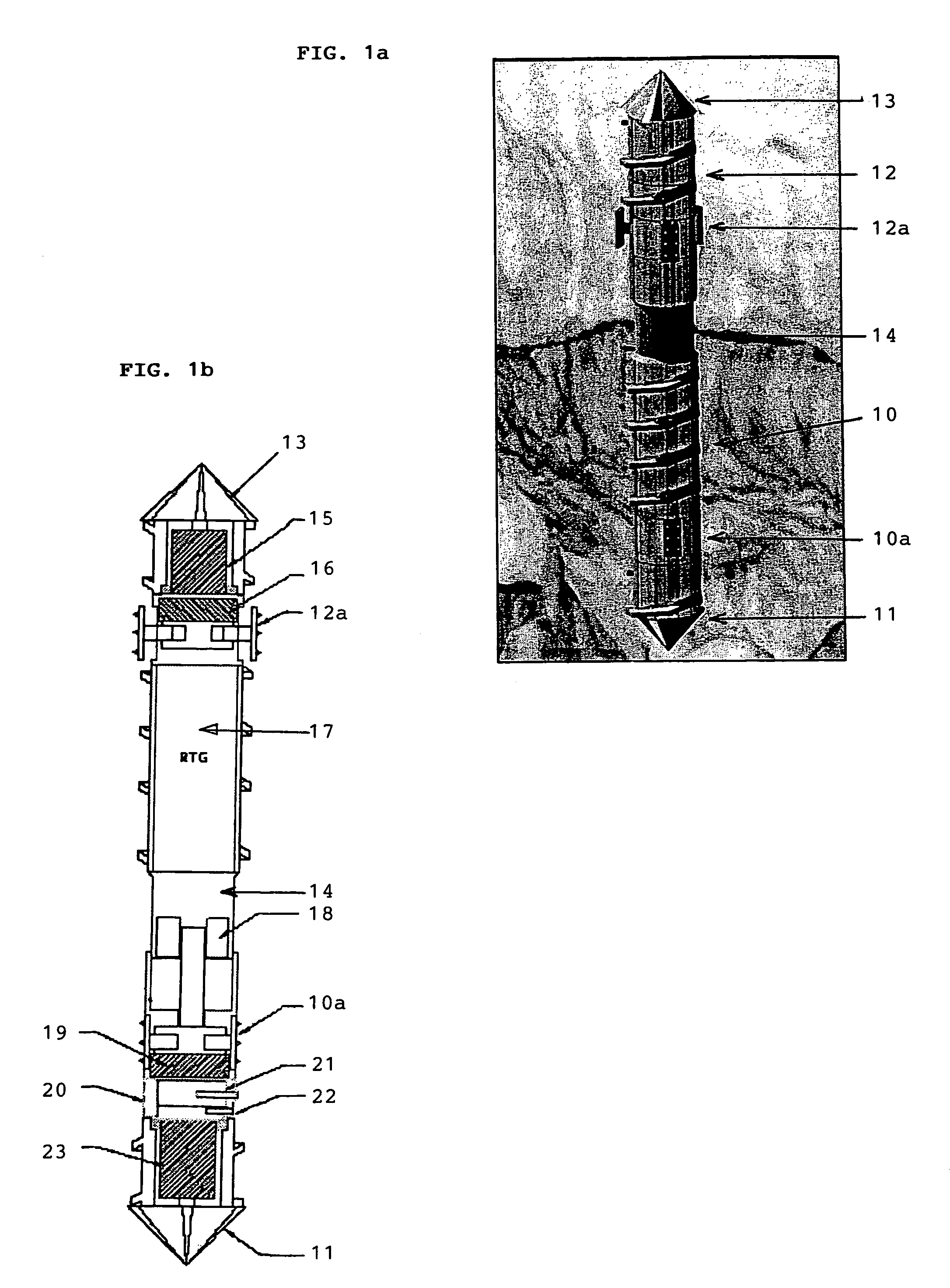
[0026]Referring to FIG. 1a, a first embodiment of an autonomous subsurface drilling device in accordance with the present invention has an on-board power source, and therefore does not require a power cord, and forward and rearward drill tips. A forward section 10 with extendable forward shoes 10a and descent drill tip 11 is spaced apart from a rearward section 12 with extendable aft shoes 12a and ascent drill tip 13. The two sections are connected by a thrust mechanism 14 which can expand and contract for the inchworm walking sequence. The figure shows the aft shoes of the rearward section in the extended position.

[0027]In FIG. 1b, the device is shown in a schematic sectional view having, in series from aft (rearward) to front (forward), ascent drill motor 15 for powering the ascent drill tip 13, aft shoe deploy motor 16 for powering the aft shoes 12a, an on-board power system 17, such as batteries, a fuel cell or a radioactive thermoelectric generator (RTG), linear actuator 18 for...


PUM


Abstract

An autonomous subsurface drilling device has spaced-apart forward and rearward “feet” sections coupled to an axial thruster mechanism between them to operate using an inchworm method of mobility. In one embodiment, forward and rearward drill sections are carried on forward and rearward “feet” sections for drilling into material in the borehole in both forward and rearward directions, to allow the device to maneuver in any direction underground. In another embodiment, a front drill section has a drill head for cutting into the borehole and conveying cuttings through a center spine tube to an on-board depository for the cuttings. The feet sections of the device employ a foot scroll drive unit to provide radial thrust and synchronous motion to the feet for gripping the borehole wall. The axial thrust mechanism has a tandem set of thrusters in which the second thruster is used to provide the thrust needed for drilling, but not walking. A steering mechanism composed of concentric inner and outer eccentric rings provided with the rearward feet section allow small corrections in both direction and magnitude to the drilling direction as drilling commences.

Description

[0001]This U.S. patent application claims the priority of U.S. Provisional Application No. 60 / 443,215 filed on Jan. 27, 2003, entitled “Inchworm Deep Drilling System”, with inventors in common herewith.[0002]The subject matter herein was developed in part under a research contract provided by the U.S. Government, National Aeronautics and Space Administration (NASA), Contract No. NAG5-12839. The U.S. Government retains certain rights in the invention.TECHNICAL FIELD[0003]This invention relates to a self-propelled drilling device which can autonomously drill deep holes while moving into the ground, in order to eliminate the need for the conventional type of drill-string drilling rig used in conventional deep drilling operations. The device is particularly desired for use in autonomous deep drilling applications such as for probes on extraterrestrial bodies, as well as for applications on Earth.BACKGROUND OF INVENTION[0004]In the prior art, there have been many types of drill platforms...

Claims


Application Information

Patent Timeline
IPC IPC(8): E21B44/00
CPCE21B49/06E21B4/18
Inventor MYRICK, THOMAS M.GOREVAN, STEPHEN
Owner HONEYBEE ROBOTICS
Learn More