Plasma display panel and production method therefor

Inactive Publication Date: 2006-06-06
PANASONIC CORP
View PDF8 Cites 12 Cited by
  • Summary
  • Abstract
  • Description
  • Claims
  • Application Information

AI Technical Summary

Benefits of technology

[0028]In particular, the use of silver electrodes, or chrome/copper/chrome electrodes as the metal elec

Problems solved by technology

CRTs, which are the most widely used among these display devices, are superior with regard to resolution and image quality, however are not suitable as devices for large screens of 40 inches or more due to their weight and depth.
On the other hand, although LCDs have superior properties of low power consumption, and low driving voltage, the production of large screen LCDs is difficult, and LCDs have limited viewing angles.
However, as the relative permittivities of these glasses were high at 10–12, there was a tendency for a large amount of current to flow during discharge, and subsequently power consumption of the PDP tended to increase.
However, because an SiO2 film is formed by an evaporating method or a spattering method, as well as forming the film to the required thickness (20–30 μm) being difficult, the formed film was easily cracked, as it was difficult to insure a sufficient pressure resistance.
However

Method used


Image

  • Plasma display panel and production method therefor
  • Plasma display panel and production method therefor
  • Plasma display panel and production method therefor

Examples


Embodiment Construction

[0034]One embodiment of the PDP of the present invention is explained below with reference to the drawings. The aim of the preferred embodiment, and the drawings of the invention of the present application which are shown below, is to show examples, and the present invention is not limited to these.

[0035](Construction of PDP)

[0036]First, the construction of PDP will be explained.

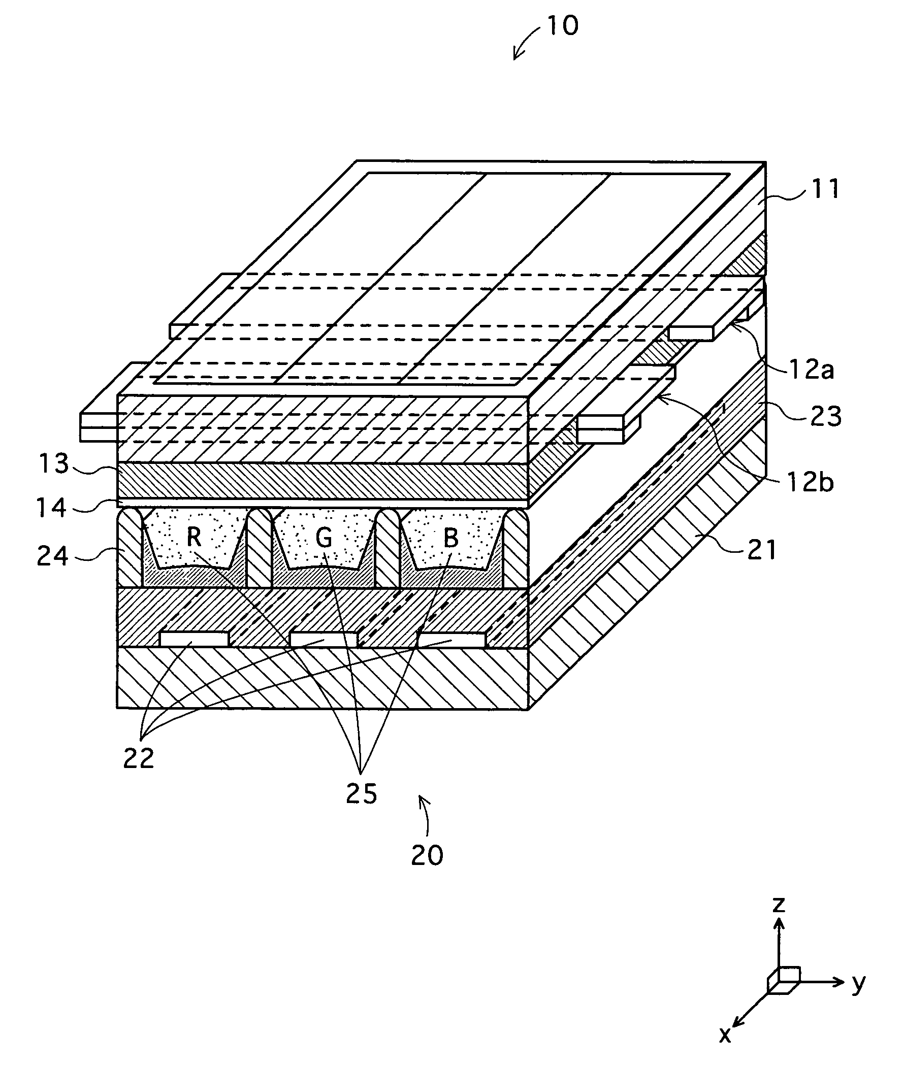
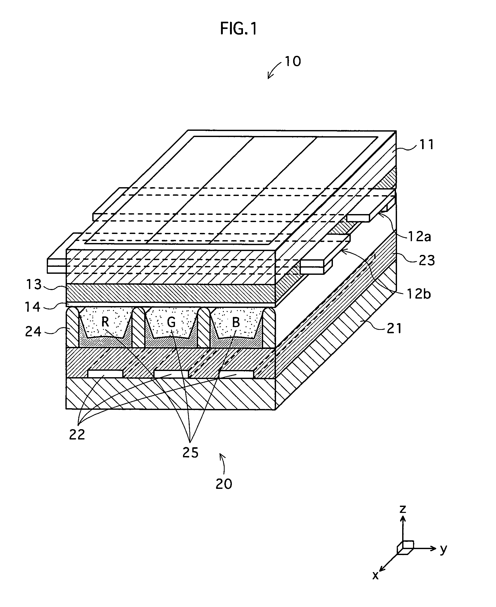
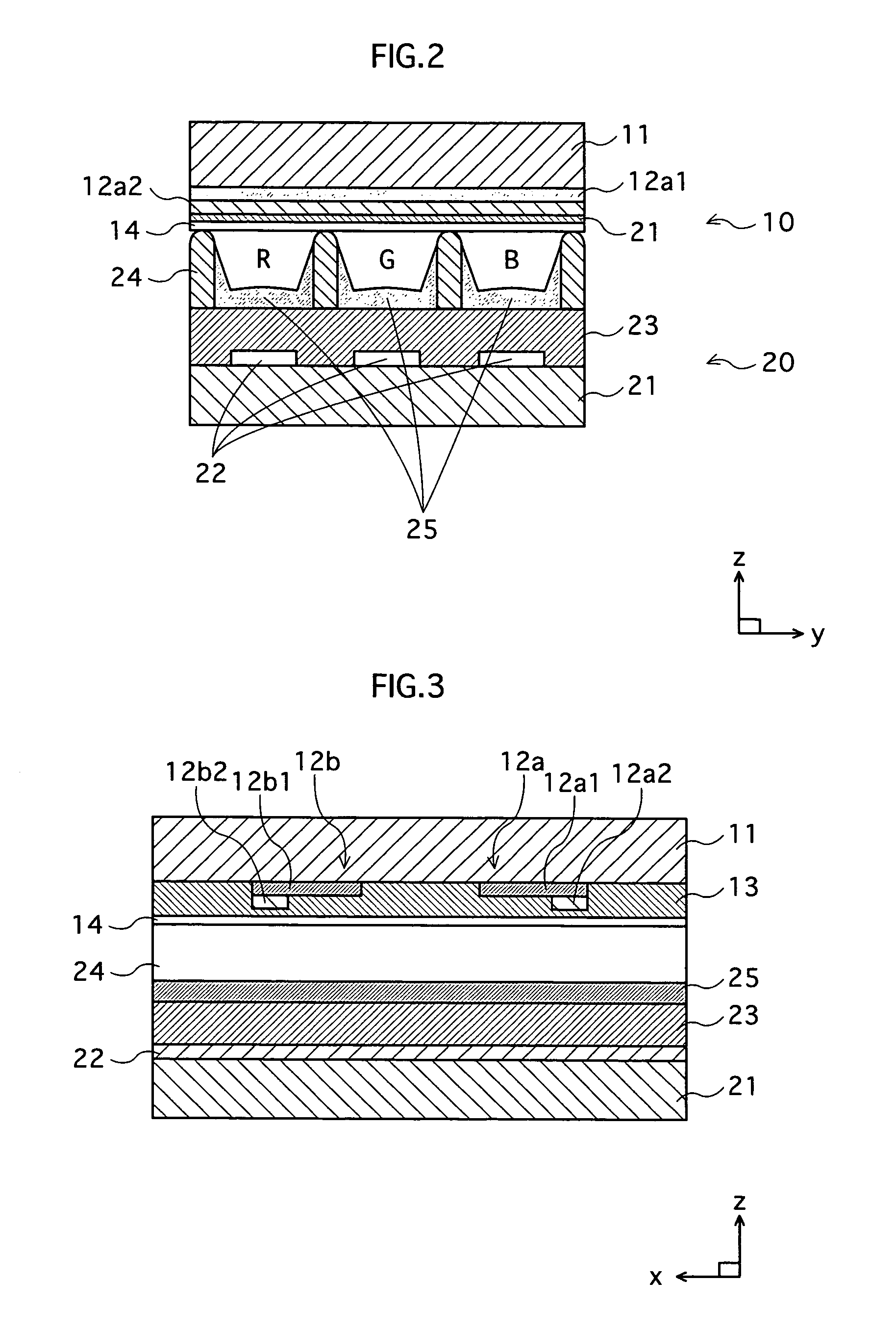
[0037]FIG. 1 is a perspective drawing of a part of the (AC) PDP of the present embodiment, FIG. 2 is a cross-sectional drawing of the PDP of FIG. 1 viewed along an x axis, and FIG. 3 is a cross-sectional drawing of the PDP of FIG. 1 viewed along a y axis.

[0038]As shown in FIG. 1, the PDP has a construction which includes a front panel 10, a back panel 20, and a front glass substrate 11 in the front panel 10, and a back glass substrate 21 in the back panel 20 which are arranged parallel to each other by barrier ribs 24 and the like. The periphery of the substrates 11, 12 are sealed together by flit glass (not...


PUM

PropertyMeasurementUnit
Fractionaaaaaaaaaa
Percent by massaaaaaaaaaa

Abstract

A plasma display panel capable of restricting the yellowing of a dielectric layer and the occurrence of dielectric breakdown, wherein glass constituting a dielectric layer uses glass containing a metal oxide MO2 capable of a trivalent or tetravalent-ion formation in glass. Accordingly, even when Ag is ionized from an electrode consisting essentially of Ag to diffuse to a dielectric layer, Ag does not aggregate to be formed into a colloid with an ionized state kept. Therefore, yellowing and dielectric breakdown caused by Ag turning to colloid can be restricted.

Description

TECHNICAL FIELD[0001]The present invention relates to a plasma display panel used for image display for a computer or television or the like.BACKGROUND ART[0002]In the field of display devices used for image display, represented by CRT displays (CRT), liquid crystal displays (LCD), and plasma display panels, much has been expected in recent years of large high-definition screens such as high vision television screens.[0003]CRTs, which are the most widely used among these display devices, are superior with regard to resolution and image quality, however are not suitable as devices for large screens of 40 inches or more due to their weight and depth. On the other hand, although LCDs have superior properties of low power consumption, and low driving voltage, the production of large screen LCDs is difficult, and LCDs have limited viewing angles. Compared with these devices, as well as PDPs having a wide viewing angle range, the production of large screen PDPs with shallow depth is relat...

Claims


Application Information

Patent Timeline
IPC IPC(8): H01J17/00H01J9/02C03C3/066C03C4/16C03C8/04C03C8/08C03C8/14C03C8/16C03C17/04H01J11/12H01J11/22H01J11/24H01J11/26H01J11/34H01J11/38H01J17/16H01J17/49
CPCC03C4/16C03C8/04C03C8/08H01J11/38C03C17/04H01J11/12C03C8/16
Inventor AOKI, MASAKIYONEHARA, HIROYUKIFUJITANI, MORIO
Owner PANASONIC CORP
Why Eureka
Try Eureka