Method of designing a logic circuit utilizing an algorithm based in C language

a logic circuit and algorithm technology, applied in the field of logic circuit design, can solve the problems of difficult to obtain the circuit intended by the designer, difficult to read the design circuit, and large scale of the circuit designed with such tools, and achieve the effect of short period of time and good quality

Inactive Publication Date: 2006-06-13
SOCIONEXT INC
View PDF7 Cites 13 Cited by
  • Summary
  • Abstract
  • Description
  • Claims
  • Application Information

AI Technical Summary

Benefits of technology

[0011]An object of the present invention is providing a method of designing a logic circuit capable of designing hardware with good quality from an algorithm description written in a pure C language efficiently in a short period of time.

Problems solved by technology

However, circuits designed with such tools are not only significantly large in scale but also low in quality, compared with circuits directly designed with RT level description.
In addition, since free control of the circuit configuration is not allowed for circuits designed with the above tools, it is very difficult to obtain a circuit intended by the designer, and also very difficult to read a designed circuit.
Therefore, the logic verification using the clock level simulator remains complicated although the speed of the verification is faster than RT level verification.
Therefore, the prior art technique fails to solve the problems relating to the RT level design, such as difficulty in response to change of specifications and complexity in examination of hardware architecture.
This complicates the concept.
In other words, the clock and the reset are unnecessary during the examination of hardware architecture and the design of hardware functions, and rather cause complexity of the examination.
This fails to make use of the advantage of the design in a C language providing a high level of abstraction.
In this situation, design will be considerably difficult without visualization of hardware in cycle operation.
This will be a major cause of reduction in simulation speed.

Method used


Image

  • Method of designing a logic circuit utilizing an algorithm based in C language
  • Method of designing a logic circuit utilizing an algorithm based in C language
  • Method of designing a logic circuit utilizing an algorithm based in C language

Examples


embodiment 1

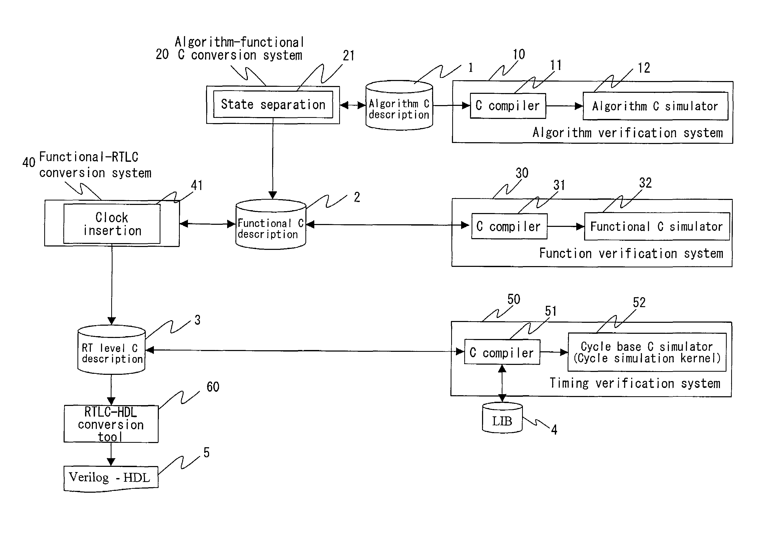
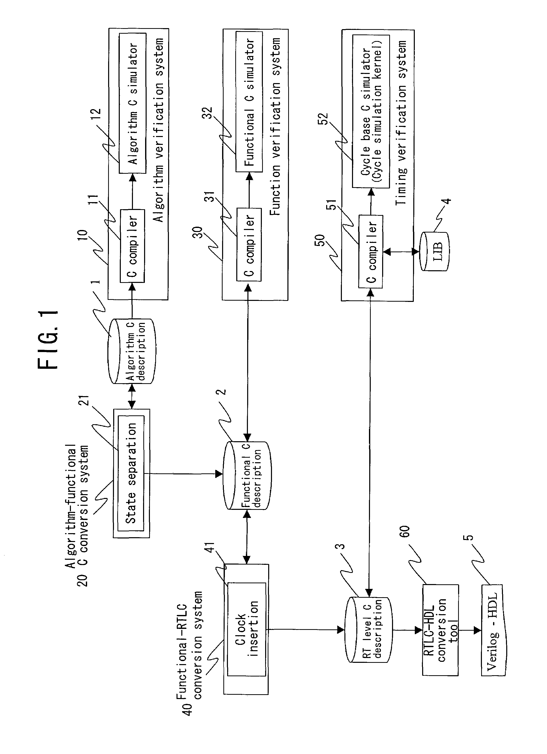
[0048]FIG. 1 illustrates a configuration of a logic circuit design system of Embodiment 1 of the present invention, which is a hardware top-down design system from C language description. Referring to FIG. 1, the reference numeral 1 denotes an algorithm C description, which is a description of an algorithm of computation or control of a logic circuit as a design object system written in a C language, 2 denotes a functional C description describing control of hardware, 3 denotes a RT level C description, which is a C language description at a register transfer (RT) level. The algorithm C description 1 is written in an existing C language such as ANSI-C and C++.

[0049]An algorithm verification system 10 generates an algorithm C simulator 12 by compiling the algorithm C description 1 with a C compiler 11. An algorithm-functional C conversion system 20, which includes a state separation means 21, converts the algorithm C description 1 into the functional C description 2. A function verif...

embodiment 2

[0083]FIG. 7 illustrates a configuration of a logic circuit design system of Embodiment 2 of the present invention, which is a hardware top-down design system from C language description. In FIG. 7, the same components as those in FIG. 1 are denoted by the same reference numerals. In FIG. 7, an algorithm-functional C conversion system 20A includes a module separation means 22, which rewrites the algorithm C description 1 for each module taking notice of hardware functions, to perform module separation. A functional-RTLC conversion system 40A includes a control / data path separation means 42, which separates a state transition description representing “control” and a computation description representing “data path” from the function C description 2.

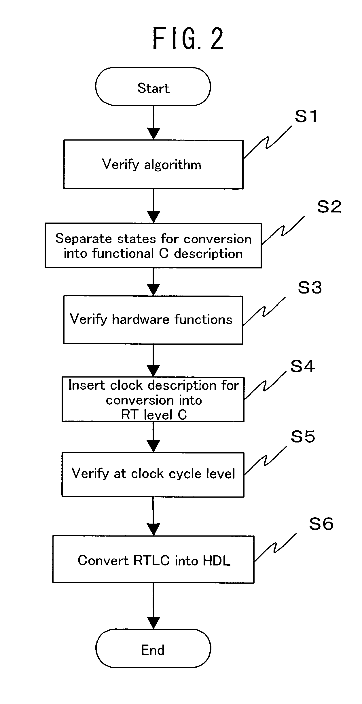
[0084]FIG. 8 is a flowchart of the logic circuit design method of this embodiment. In FIG. 8, the same process steps as those in FIG. 2 are denoted by the same reference numerals. In FIG. 8, step S7 is a module separation determination step...

embodiment 3

[0102]FIG. 13 illustrates a configuration of a logic circuit design system of Embodiment 3 of the present invention, which is a hardware top-down design system from C language description. In FIG. 13, the same components as those in FIG. 7 are denoted by the same reference numerals. In FIG. 13, a functional-SystemC conversion system 40B, a SystemC verification system 50A and a SystemC synthesis tool 70 are provided in place of the functional-RTLC conversion system 40A, the timing verification system 50 and the conversion tool 60 in FIG. 7. The functional-SystemC conversion system 40B includes the control / data path separation means 42 and a sensitive description insertion means 43 for sensitive designation, and converts the functional C description 2 into a SystemC description 6. The SystemC verification system 50A compiles the SystemC description 6 with a C compiler 53 using a SystemC library 7, to generate a SystemC simulator 54. The SystemC synthesis tool 70, which is made of a Sy...


PUM


Abstract

An algorithm C description describing an algorithm of computation or control of a logic circuit in a C language is split into a plurality of states in units of processing, and the execution order of the split processing is described as state transition, to generate a functional C description with a control description embedded therein. A clock description as the conception of time is inserted in the functional C description, to be converted into a RT level C description. The RT level C description is converted into a RT level description in HDL with an existing conversion tool.

Description

BACKGROUND OF THE INVENTION[0001]The present invention relates to logic circuit design, and more particularly, to technology of top-down design from C language description.[0002]Conventionally, hardware of a logic circuit has been designed with a hardware description language (HDL) such as Verilog-HDL and VHDL. In recent years, with the advent of system level description languages called SpecC and SystemC, hardware design with a C language has become a focus of attention.[0003]One of prior art techniques provides a language with which simulation can be performed at an intermediate level between algorithm description and register transfer (RT) level description (disclosed in Japanese Laid-Open Patent Publication No. 2001-109788). FIG. 16 illustrates a conventional logic simulation system, in which an algorithm description 103 is degraded to clock level description. A plurality of functions of the algorithm description 103 are disassembled into partial functions operable in a unit clo...

Claims


Application Information

Patent Timeline
Patent Type & Authority Patents(United States)
IPC IPC(8): G06F17/50G06F9/45H01L21/82
CPCG06F17/5045G06F30/30
Inventor TOJIMA, MASAYOSHI
Owner SOCIONEXT INC
Why Eureka
Try Eureka