Decoding method, decoding apparatus and digital transmission system of product code

a technology of decoding apparatus and product code, applied in the direction of coding, digital signal error detection/correction, code conversion, etc., can solve the problems of difficult to be built into the apparatus, inability to accurately calculate the soft output value, and calculation of the squared euclidean distance, etc., to achieve accurate calculation of soft output value, reduce circuit scale, and efficiently utilize the candidate codeword

Inactive Publication Date: 2006-06-27
MITSUBISHI ELECTRIC CORP
View PDF7 Cites 18 Cited by
  • Summary
  • Abstract
  • Description
  • Claims
  • Application Information

AI Technical Summary

Benefits of technology

[0054]The present invention is implemented to solve the foregoing problems. It is therefore an object of the present invention to provide a decoding method, decoding apparatus and digital transmission system of a product code capable of calculating the soft output values accurately by efficiently utilizing the candidate codewords generated, and capable of reducing the circuit scale by reducing the amount of operation.
[0055]According to a first aspect of the present invention, there is provided a decoding method including the steps of generating a codeword from positions of soft input values detected by a detection step and the syndromes computed by a syndrome calculation step to generate error position sets of a data sequence, and calculating correlation mismatch amounts by adding the soft input values at the error positions included in the error position sets of the data sequence; and updating correction information in accordance with the error position sets and the correlation mismatch amounts. Thus, the decoding method offers an advantage of being able to calculate the soft output values accurately by utilizing the generated codeword candidates efficiently, and to reduce the calculation amount and the circuit scale.
[0056]According to a second aspect of the present invention, there is provided a decoding apparatus including: C1 code decoding means for receiving correction information and demodulation data multiplexed by multiplexing means, for updating the correction information by carrying out soft input / soft output decoding of the C1 code, and for decoding a binary linear code from the updated correction information and the demodulation data. Thus, the decoding apparatus offers an advantage of being able to calculate the soft output values accurately by utilizing the generated codeword candidates efficiently, and to reduce the calculation amount and the circuit scale.
[0057]According to a third aspect of the present invention, there is provided a digital transmission system having a decoding apparatus including: C1 code decoding means for receiving correction information and demodulation data multiplexed by multiplexing means, for updating the correction information by carrying out soft input / soft output decoding of the C1 code, and for decoding a binary linear code from the updated correction information and the demodulation data. Thus, the digital transmission system offers an advantage of being able to construct a highly reliable digital transmission system.

Problems solved by technology

In general, high performance correcting codes require complicated decoding, which makes it difficult to be built into an apparatus.
With the foregoing configuration, the conventional decoding method of a product code has a problem of being unable to reflect the information provided by the candidate codewords other than the codeword [Cd] and the concurrent codeword [Cc] closest to the soft input vectors in terms of the squared Euclidean distance among the many codewords found at the codeword generating step, thereby being unable to calculate the soft output values accurately.
The amount of calculation of the squared Euclidean distance, however, is large, and this presents a problem of increasing the circuit scale when implementing the calculation by hardware.
Furthermore, since the foregoing decoding method is developed with only the floating-point operation in mind, it has a problem of being unsuitable for the fixed-point operation.

Method used


Image

  • Decoding method, decoding apparatus and digital transmission system of product code
  • Decoding method, decoding apparatus and digital transmission system of product code
  • Decoding method, decoding apparatus and digital transmission system of product code

Examples


embodiment 1

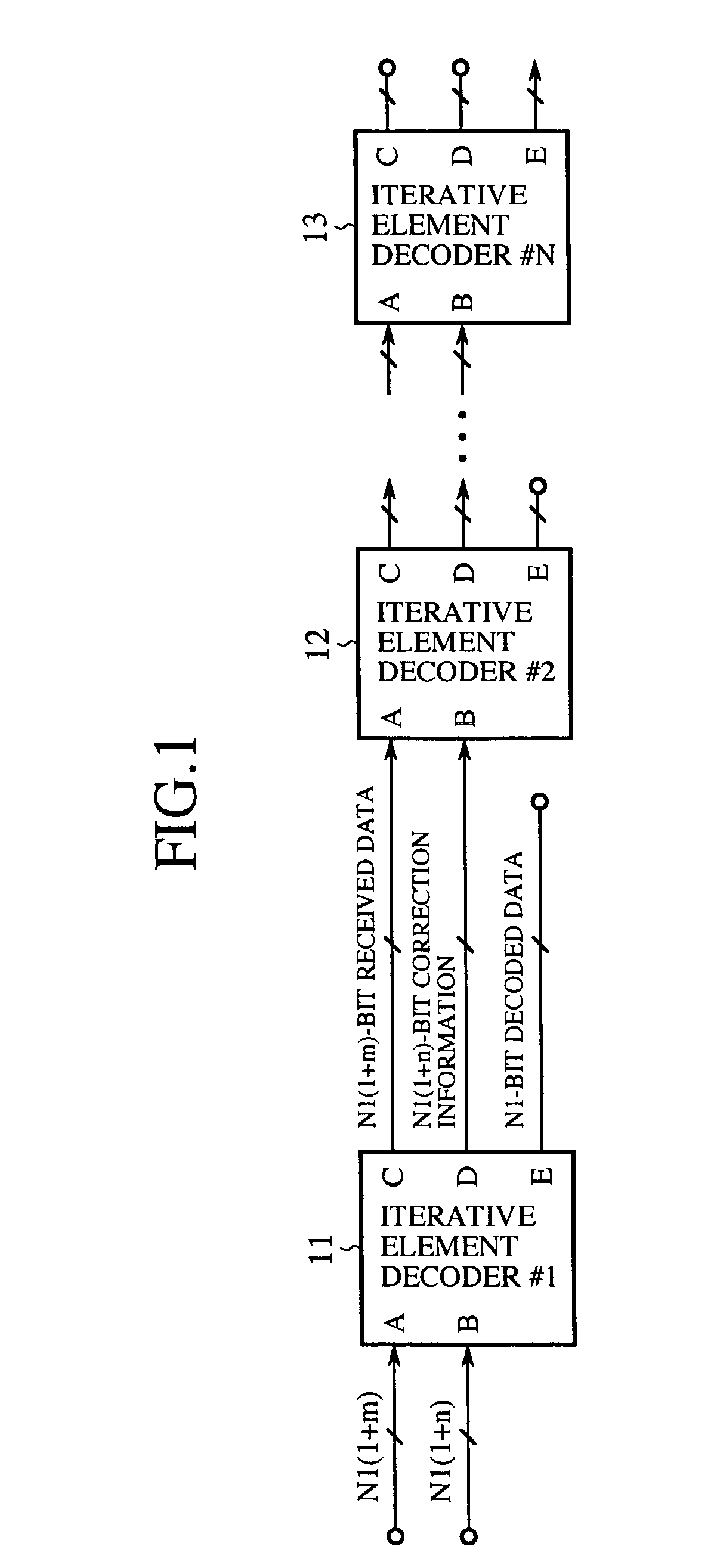
[0071]FIG. 1 is a block diagram showing a configuration of a decoding apparatus of a product code of an embodiment 1 in accordance with the present invention. In FIG. 1, reference numerals 11, 12 and 13 each designate an iterative element decoder of a product code. An input terminal A of each of the iterative element decoders 11, 12 and 13 is provided for inputting demodulation data; an input terminal B is provided for inputting correction information used for decoding; an output terminal C is provided for outputting demodulation data which is supplied from the terminal A and undergoes the decoding; an output terminal D is provided for outputting updated correction information; and an output terminal E is provided for outputting the decoded data.

[0072]Next, the operation will be described.

[0073]Here, the description is made using a product code under the assumption that both C1 code and C2 code are a Hamming code, and the parity check matrix of the C1 code is H1, and that of the C2 ...

embodiment 2

[0180]The binary linear code constituting the product code, the C1 code and C2 code, is an error detection code as well as an error correction code. In particular, the error detection has an advantage of being implemented easily by computing the syndromes. Utilizing the advantage, the error detection of the product code can be achieved easily by installing a syndrome calculation circuit for the C1 code or C2 code after the decoding apparatus of a product code described in the foregoing embodiment 1.

[0181]In this case, if all the syndromes of the element codes are zero, a decision is made that no error occurs, that is, the decoded data output from the decoding apparatus is correct. In contrast, if any element code includes the syndromes of nonzero, a decision is made that the decoded data is incorrect. In the case where the error is detected, it is better to discard the decoded data and to halt the operation at the error detection.

[0182]Employing the soft input / soft output decoding u...

embodiment 3

[0184]FIG. 8 is a block diagram showing a configuration of a digital transmission system of an embodiment 3 in accordance with the present invention. In FIG. 8, the reference numeral 60 designates a transmitter; 61 designates an encoder for generating a product code by encoding the input information data; 62 designates a modulator for converting the product code generated by the encoder 61 to a signal suitable for a communication channel 63; 63 designates the communication channel; 64 designates a demodulator for demodulating the received signal fed from the communication channel 63 and supplies the demodulation data to a decoder 65; 65 designates the decoder for decoding the demodulation data fed from the demodulator 64 to estimate the information data; 70 designates a receiver; 71 designates a retransmission controller; 72 designates a retransmission buffer; 73 designates a retransmission controller; 74 designates a receiving buffer; and 75 designates an error detector. The encode...


PUM

PropertyMeasurementUnit
speedaaaaaaaaaa
lengthaaaaaaaaaa
information lengthaaaaaaaaaa

Abstract

A decoding apparatus generates error position sets of data sequence by generating a codeword from positions of soft input values output from a low reliability position detecting circuit and from syndromes computed by a syndrome calculation circuit. The recording apparatus further includes a codeword candidate generating circuit that computes correlation mismatch amounts by adding soft input values at the error positions contained in the error position sets, and updates the correction information according to the error position sets and correlation mismatch amounts. The decoding apparatus can calculate the soft output values accurately by utilizing the generated codeword candidates efficiently, and reduce the circuit scale by decreasing the amount of computation.

Description

BACKGROUND OF THE INVENTION[0001]1. Field of the Invention[0002]The present invention relates to a decoding method, decoding apparatus and digital transmission system of a product code for improving the reliability of a digital communication system or digital recording system.[0003]2. Description of Related Art[0004]Although error-correcting codes such as Reed-Solomon codes have been utilized to improve reliability of digital communication / recording systems, more powerful error-correcting codes have been required recently to meet increasing speed and capacity of the systems.[0005]In general, high performance correcting codes require complicated decoding, which makes it difficult to be built into an apparatus. However, using concatenated codes or product codes makes it possible to implement high-performance coding rather easily. In particular, the product codes have an advantage that they have large redundancy and error-correcting power because of the double encoding of information d...

Claims


Application Information

Patent Timeline
Patent Type & Authority Patents(United States)
IPC IPC(8): H03M13/00G06F11/10G11B20/18H03M13/15H03M13/29H03M13/45H04L1/00H04L1/18
CPCH03M13/2909H03M13/2927H03M13/2948H03M13/3738H03M13/45H03M13/451H03M13/6306H03M13/6561H04L1/005H04L1/0066H03M13/151H03M13/136H04L1/1874H03M13/152H03M13/19H04L1/1835
Inventor FUJITA, HACHIROMIYATA, YOSHIKUNINAKAMURA, TAKAHIKOYOSHIDA, HIDEO
Owner MITSUBISHI ELECTRIC CORP
Why Eureka
Try Eureka