
Scatterometry monitor in cluster process tool environment for advanced process control (APC)

a technology of process control and clustering, applied in the field of semiconductor fabrication, can solve the problems of undetected defects, affecting the performance of finished products, and generating defects, so as to improve process control, productivity and performance of wafer fabrication systems, the critical dimension(s) of resists can be undesired altered

Active Publication Date: 2006-07-11
ADVANCED MICRO DEVICES INC
View PDF22 Cites 42 Cited by
  • Summary
  • Abstract
  • Description
  • Claims
  • Application Information

AI Technical Summary

Benefits of technology

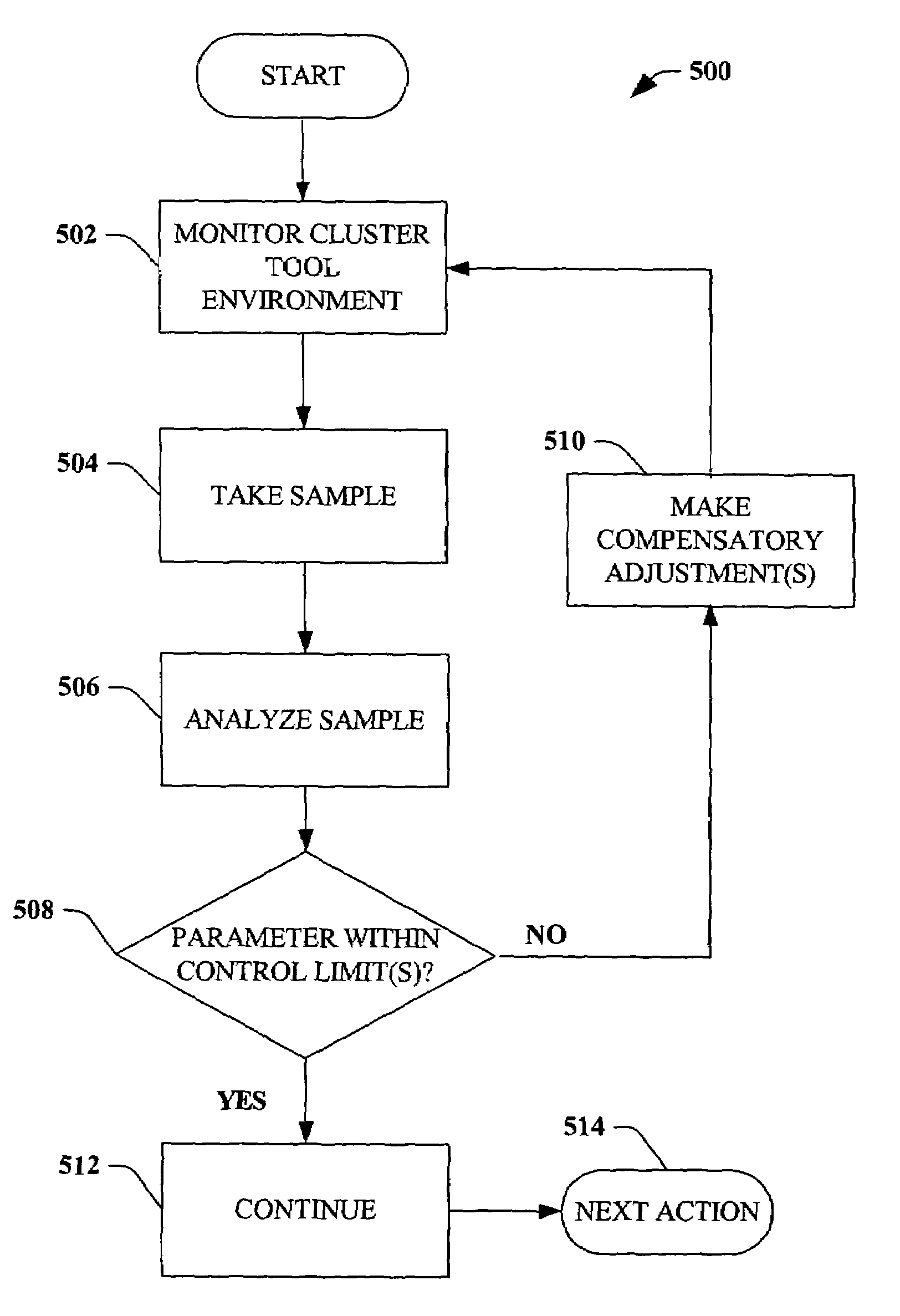
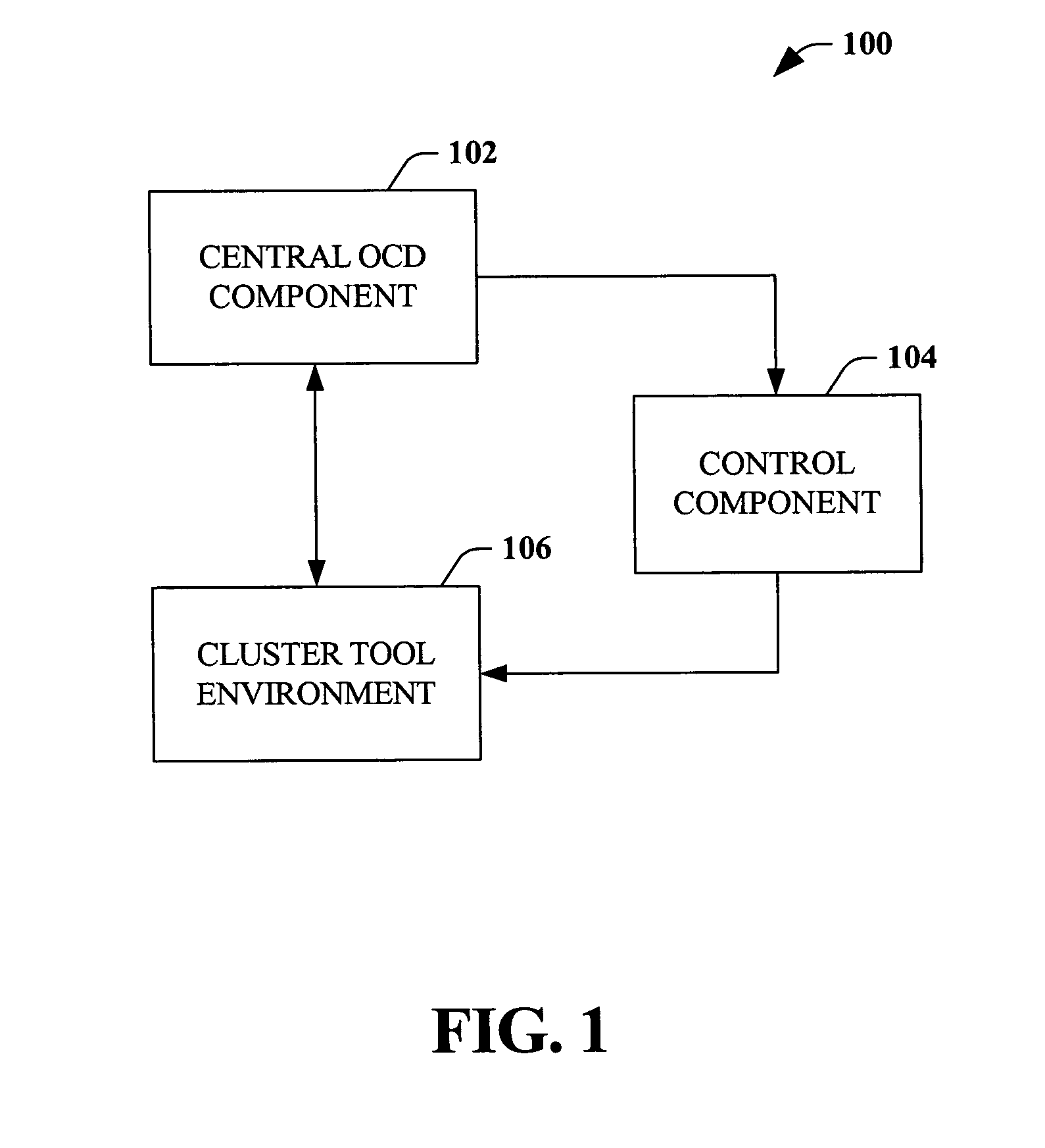
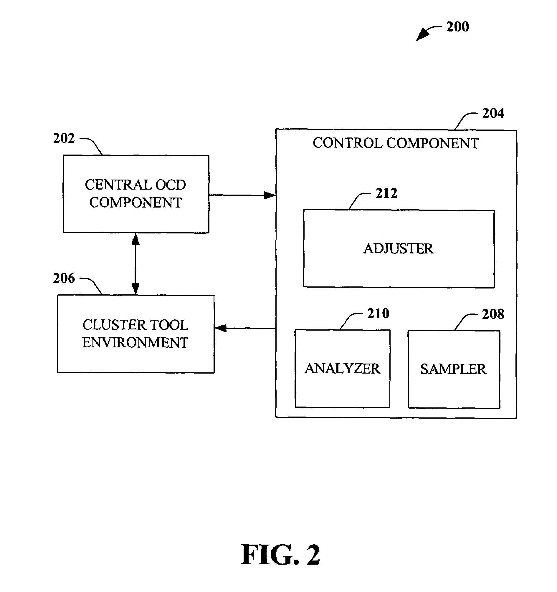
[0011]The present invention generally relates to systems and methods that improve process control by providing an in-situ monitor that employs feedback / feed-forward loop(s) to more effectively enhance advanced process control (APC). Optical scatterometry (OCD), for example, offers many advantages in semiconductor processing, such as increased throughput, relatively low cost, and three-dimensional spatial information (e.g., thickness, critical dimension, profile, etc.). As a result, scatterometry plays a major role in APC in wafer fabrication systems.
[0013]According to another aspect of the invention, OCD can be employed as an in-situ monitor for a stepper system in a cluster tool environment. For example, if a parameter of the stepper process is determined to be outside of a predetermined tolerance, the APC system can initiate compensatory adjustments to mitigate the effects of the out-of-control parameter. According to this aspect, an OCD component can be employed to determine whether, for example, whether an exposure period is of a proper duration, whether an exposure source is properly focused, etc. Based on such information, the APC system can initiate a feedback / feed-forward loop to correct any deviant parameters of the stepper system, and, thereby, improve wafer throughput, reduce wafer fabrication costs, etc.
[0016]According to still another aspect of the present invention, an OCD component can monitor a chemical bath in-situ in a cluster tool environment to determine whether parameters associated therewith are within control tolerances. For example, the OCD component can monitor a concentration of polymers in the chemical bath. If a particular concentration is not within a control tolerance, an APC system can initiate corrective action such refill of the bath, change of a filter, substitution of a particular chemical, etc. In this manner, the present invention can improve process control, productivity, and performance of wafer fabrication systems.
[0017]According yet another aspect, an OCD component can initiate corrective action at a stage of wafer fabrication subsequent to the stage at which an out-of-control state is detected. For example, if the temperature of a hot plate in a track system is determined to be above a target tolerance, then the critical dimension(s) of the resist can be undesirably altered. The present invention can initiate compensatory action at a subsequent time, such as during exposure, so that the exposure time is adjusted to correct any deviation in CD caused by the out-of-control temperature of the hot plate. Additionally, the temperature of the hot plate can be corrected for subsequent wafers.

Problems solved by technology

Such defects may be generated by the fabrication process utilized to produce the mask or reticle as well as during subsequent handling and processing.
Critical dimensions of the patterned resist, such as line widths, affect the performance of the finished product and are sensitive to processing conditions.
Many of the conditions that affect critical dimensions are difficult to control, often resulting in variations from batch to batch.
Often, a defect goes undetected until a wafer is completely manufactured, and is only discovered upon failure of the final product.
Furthermore, transferring a wafer to an inspection tool after each individual process is inefficient and cost-prohibitive.
An unsatisfied need exists in the art for systems and methods that facilitate inline, continuous, and centralized wafer inspection and / or correction.

Method used


Image

  • Scatterometry monitor in cluster process tool environment for advanced process control (APC)
  • Scatterometry monitor in cluster process tool environment for advanced process control (APC)
  • Scatterometry monitor in cluster process tool environment for advanced process control (APC)

Examples


Embodiment Construction

[0032]The present invention is now described with reference to the drawings, wherein like reference numerals are used to refer to like elements throughout. In the following description, for purposes of explanation, numerous specific details are set forth in order to provide a thorough understanding of the present invention. It may be evident, however, that the present invention may be practiced without these specific details. In other instances, well-known structures and devices are shown in block diagram form in order to facilitate describing the present invention.

[0033]As used in this application, the terms “component” and “system” are intended to refer to a computer-related entity, either hardware, a combination of hardware and software, software, or software in execution. For example, a component may be, but is not limited to being, a process running on a processor, a processor, an object, an executable, a thread of execution, a program, and a computer. By way of illustration, b...


PUM


Abstract

Systems and methods that improve process control in semiconductor manufacturing are disclosed. According to an aspect of the invention, conditions in a cluster tool environment and / or a wafer therein can be monitored in-situ via, for example, a scatterometry system, to determine whether parameters associated with wafer production are within control limits. A cluster tool environment can include, for example, a lithography track, a stepper, a plasma etcher, a cleaning tool, a chemical bath, etc. If an out-of-control condition is detected, either associated with a tool in the cluster tool environment or with the wafer itself, compensatory measures can be taken to correct the out-of-control condition. The invention can further employ feedback / feed-forward loop(s) to facilitate compensatory action in order to improve process control.

Description

TECHNICAL FIELD[0001]The present invention relates generally to semiconductor fabrication, and more particularly, to systems and methods that improve process controls and efficiency in a wafer fabrication environment.BACKGROUND OF THE INVENTION[0002]In the semiconductor industry, there is a continuing trend toward higher device densities. To achieve these higher device densities there have been, and continue to be, efforts toward scaling down the device dimensions on semiconductor wafers. This continuing trend has also led to advanced monitoring and quality control of every step of the semiconductor manufacturing process.[0003]High resolution lithographic processes are used to achieve small features. In general, lithography refers to processes for pattern transfer between various media. In lithography for integrated circuit fabrication, a silicon slice, the wafer, is coated uniformly with a radiation-sensitive film, the resist. The film is selectively exposed with radiation (such as...

Claims


Application Information

Patent Timeline
IPC IPC(8): G06F19/00
CPCH01L21/67253G03F7/70525
Inventor PHAN, KHOI A.SINGH, BHANWARSUBRAMANIAN, RAMKUMAR
Owner ADVANCED MICRO DEVICES INC
Learn More