

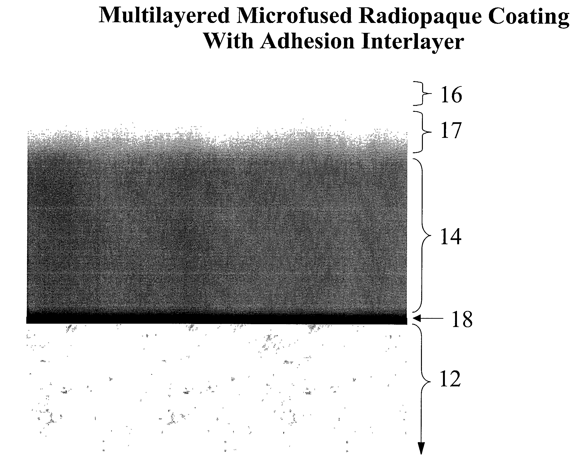
Multi-layered radiopaque coating on intravascular devices
a radiopaque coating and intravascular technology, applied in blood vessels, prostheses, applications, etc., can solve the problems of band looseness, shifting, falling off, and undesirable effect on other device characteristics, so as to prevent exposure promote the bonding of the radiopaque layer, and enhance the bonding of the capping layer
- Summary
- Abstract
- Description
- Claims
- Application Information
AI Technical Summary
Benefits of technology
Problems solved by technology
Method used
Image

Examples
Embodiment Construction
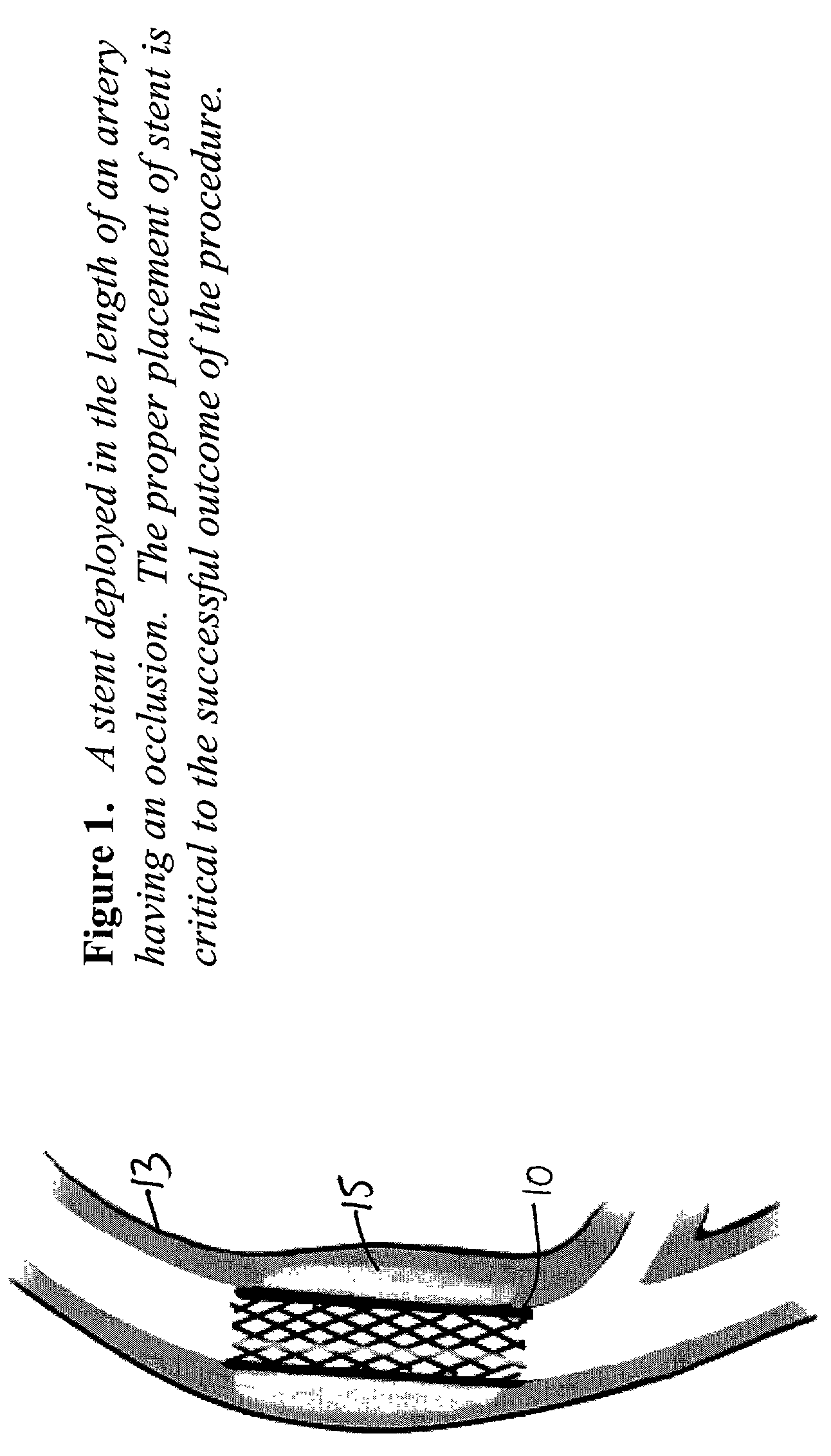
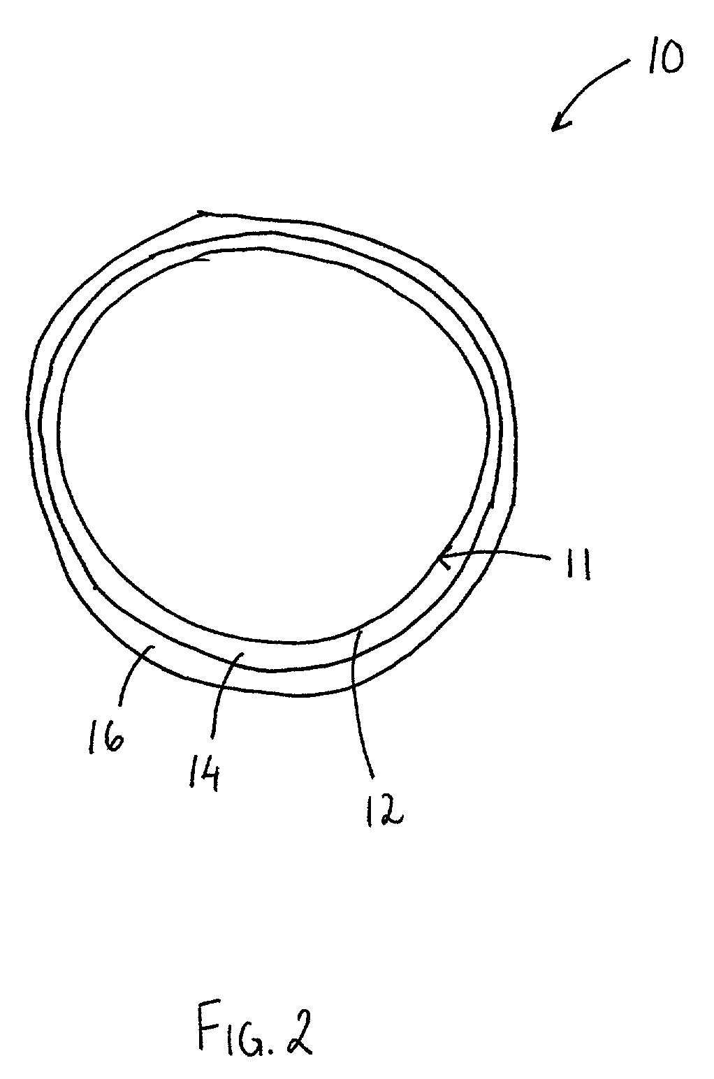
[0022]In FIG. 1, there is shown an intravascular device 10 in accordance with one embodiment of the present invention. The device 10, as illustrated by the cross sectional view in FIG. 2, includes a body 11 having substrate surface 12, a layer 14 of a radiopaque material on the substrate surface 12, and a capping layer 16 on the layer 14 of the radiopaque material.
[0023]The device 10, illustrated in FIG. 1 as a stent, may be made so that the body 11 can be provided with the ability to expand while, at the same time, being flexible, so that the device 10 can be deployed to a site of stenosis 15 within, for instance, a coronary artery 13. In addition, the body 11 of device 10 may be made from a strong material sufficient to provide adequate radial strength at the site of stenosis to prevent closure. In one embodiment, the body 11 of device 10 may be made from a metallic material, which includes, but is not limited to, stainless steel, nickel-based steel, cobalt-chrome, titanium alloys...
PUM
| Property | Measurement | Unit |
|---|---|---|
| thickness | aaaaa | aaaaa |
| thickness | aaaaa | aaaaa |
| thickness | aaaaa | aaaaa |
Abstract
Description
Claims
Application Information