Aquaculture nitrogen waste removal

a technology of nitrogen waste and aquaculture, applied in the field of aquaculture, can solve the problems of high nitrate effluent discharge, high cost, and complex discharge permits

Active Publication Date: 2006-08-01
UNIV OF MARYLAND BALTIMORE COUNTY
View PDF16 Cites 38 Cited by
  • Summary
  • Abstract
  • Description
  • Claims
  • Application Information

AI Technical Summary

Problems solved by technology

While nitrate is considerably less toxic than ammonium or nitrate, it can also be a problem.
Second, in systems where natural sea water is unavailable, deionized water and sea salts must be mixed, which may incur heavy additional costs.
However, the discharge of the high nitrate effluent is potentially a problem, since salt water cannot typically be discharged into a sewage system or a fluvial system.
Further, there is a growing environmental concern about the discharge of nitrogenous waste.
Discharge permits may be complex and often require very stringent pollutant limits.
However, because denitrification is exclusively an anaerobic process, the process is rarely included in any biofiltration systems that require oxygenated water, as is the case in aquaculture systems.
Additionally, alcohols, volatile fatty acids and sugars, which are often used as carbon sources for such systems, often lead to bacterial blooms, toxic by-products, among other problems, and result in elevated system costs.
Thus, the disadvantages of stimulating denitrifying activity often outweigh the advantages.

Method used


Image

  • Aquaculture nitrogen waste removal
  • Aquaculture nitrogen waste removal
  • Aquaculture nitrogen waste removal

Examples


example 1

Nitrification and Denitrification in a Recirculating Aquaculture System

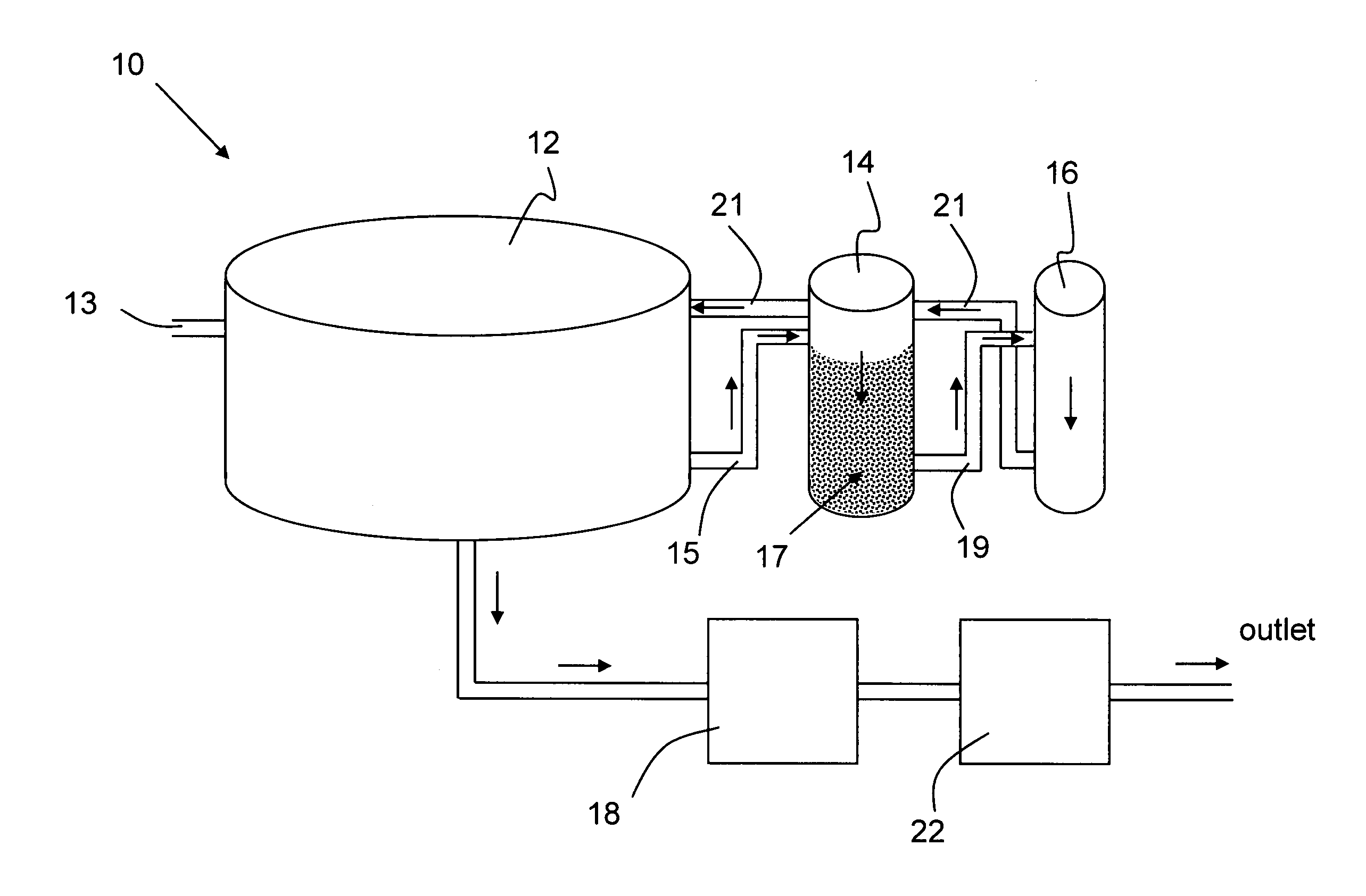
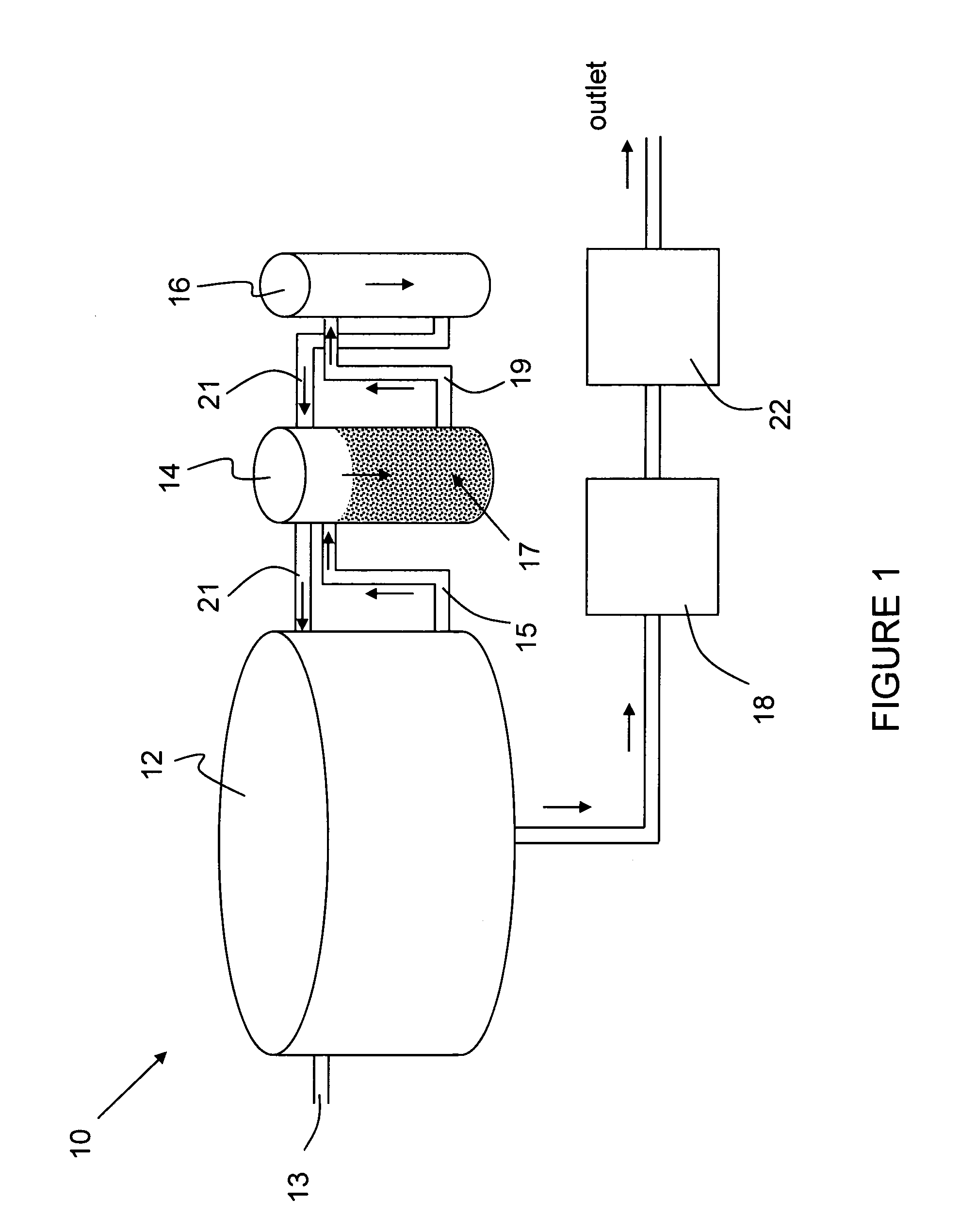
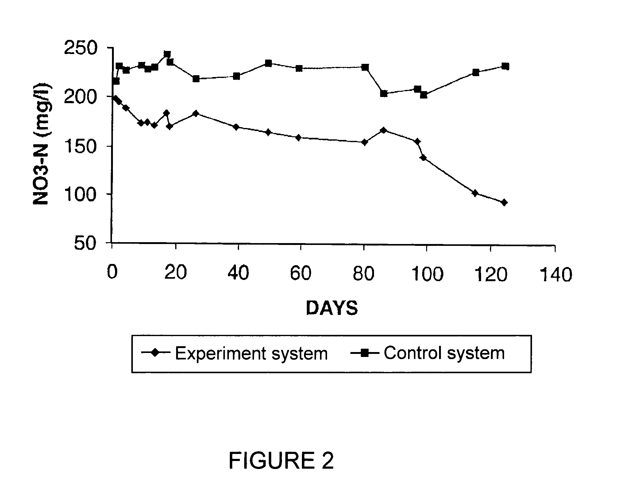
[0053]A 5-m3 circular fiberglass tank containing gilthead seabream, Sparus aurata, was operated at a density of 80 kg / m3 and feeding rate of 6 kg / day. The tank was connected to a 2-m3 moving bed bioreactor filled with 1 m3 of polyethylene beads having a specific surface area of 500 m2 / m3 (4.86 cm2 / bead) (Water Management Technologies, Baton Rouge, La., USA). A flow rate of 10 m3 / h was set to enable two exchanges of water per hour through the filter. After four months of operation, 3000 beads from this high organic load MBB were transferred to a small experimental salt water system having a filter volume of 5 liter and tank volume of 150 liter. For nitrification activity, incubations were performed in a moving bed bioreactor of the present invention under aerobic conditions with the addition of 3 mg NH3—N / L.

[0054]An anaerobic denitrifying moving bed bioreactor was directly attached to the aerobic biofilter reactor...

example 2

[0056]The two-stage biofiltration system comprising a aerobic biofilter reactor and an anaerobic biofilter reactor was used with two 4000 L tanks in which seabream were grown at 40–50 kg / m3 and fed daily at 1% of their body weight. During a four-month experimental period, daily water exchanges were obtained that averaged as low as approx. 1% of the tank volume. This water exchange was significantly lower than the 7% to 10% generally required by the system and this reduction in water exchange reduces the costs associated with salt from as high as 25% to as little as 3% of the total production cost, thereby considerably enhancing the profitability of such systems. Variations from the above described conditions are possible and can be varied by one of ordinary skill in the art. The examples provided are for illustration of the instant invention and are not intended to limit the scope of the disclosed invention


PUM

PropertyMeasurementUnit
diameteraaaaaaaaaa
concentrationaaaaaaaaaa
thicknessaaaaaaaaaa

Abstract

The present invention relates to a two-stage biofilter reactor system for removing nitrogenous compounds from a recirculating aquaculture system. The system includes a aerobic nitrification unit and a downstream anaerobic denitrification unit, wherein both units have a mobile bed of suspended media whereon bacteria can grow and reduce nitrate and / or ammonia levels in the recirculating aquaculture system. Use of the two-stage system has the advantage of reducing the water exchange rates and consumption of salt when maintaining a saline effluent.

Description

CROSS-REFERENCE TO RELATED APPLICATIONS[0001]This application claims priority from U.S. Provisional Patent Application No. 60 / 460,228 filed on Apr. 3, 2003 in the names of Harold J. Schreier, Yossi Tal and Yonathan Zohar for “AQUACULTURE NITROGEN WASTE REMOVAL,” the contents of which are incorporated by reference herein for all purposes.BACKGROUND OF THE INVENTION[0002]1. Field of the Invention[0003]The present invention relates to nitrogen removal, and more particularly, to an aquaculture system including a denitrification unit for denitrifying aquatic effluent by anaerobic bacteria in combination with a nitrification unit.[0004]2. Description of the Related Art[0005]The development of technology and protocols that will enable the aquaculture industry to expand production of aquatic species in urban recirculating systems requires systematic examination of each aspect of said aquatic systems. Many conventional aquaculture systems are known and can be classified in one of two ways; c...

Claims


Application Information

Patent Timeline
Patent Type & Authority Patents(United States)
IPC IPC(8): C02F3/32A01K63/04C02F3/12C02F3/28C02F3/30
CPCA01K63/045C02F3/302C02F3/2806C02F3/087A01K63/04Y02W10/10
Inventor SCHREIER, HAROLD J.TAL, YOSSIZOHAR, YONATHAN
Owner UNIV OF MARYLAND BALTIMORE COUNTY
Why Eureka
Try Eureka