Variable blade manufacturing method and variable blade in VGS type turbo charger

a manufacturing method and turbo charger technology, applied in the field of vgs turbochargers, can solve the problems of difficult to produce an effect of the turbocharger, the turbocharger hardly functions, and the engine cannot avoid giving a slow-moving feeling, etc., to achieve accurate and secure regulation of the flow rate of exhaust gas, high heat resistance, and high accuracy

Inactive Publication Date: 2006-08-15
AKITA FINE BLANKING
View PDF6 Cites 17 Cited by
  • Summary
  • Abstract
  • Description
  • Claims
  • Application Information

AI Technical Summary

Benefits of technology

[0034]In accordance with the invention, it is possible to actually mass produce the VGS turbocharger having a high heat resistance. Further, since the adjustable blade having a high accuracy is incorporate...

Problems solved by technology

In the case of an engine capable of running at up to a high rotational speed region, when the engine is running at low rotational speeds, the exhaust turbine of the turbocharger hardly functions due to the reduced flow rate of the exhaust gas, so that the engine can not avoid giving a slow-moving feeling until the exhaust turbine runs efficiently, and necessitating a subsequent time or a so-called turbo-lag before the turbine rapidly reaches the full-running state.
Furthermore, in the case of a diesel engine which runs inherently at low rotational speeds, there is a disadvantage in that it is difficult to produce an effect of the turbocharger.
However, in the technique using cutting operations applied to the shaped material, the following problems arise.
However, since such a material is generally difficult to cut and therefore requires a lot of time to cut it, there is a problem that a lot of trouble is taken for processing it.
In addition, since about ten to fifteen adjustable blades are required in one turbocharger, it is necessary to manufacture 300,000 to 450,000 adjustable blades a month in the case that about 30,000 motor vehicle...

Method used


Image

  • Variable blade manufacturing method and variable blade in VGS type turbo charger
  • Variable blade manufacturing method and variable blade in VGS type turbo charger
  • Variable blade manufacturing method and variable blade in VGS type turbo charger

Examples


embodiment 1

(1) Embodiment 1

(i) Preparing Step of Shaped Material (Blank)

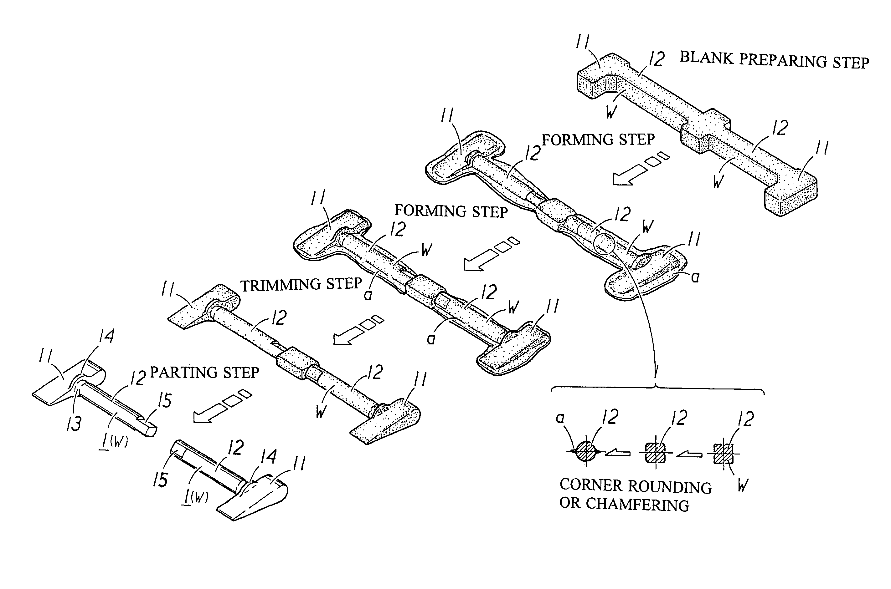
[0054]This step is a step of preparing the metal shaped material W which is integrally provided with the blade portion forming section 11a and the shaft portion forming section 12a, and which is a starting form for the adjustable blade 1. In this embodiment, the shaped material W is constituted by the blank punched out from the metal material having an approximately constant thickness, for example, by fine blanking (which is known as a precise punching method, and is hereinafter abbreviated as FB). Of course, the blank (shaped material W) is punched out so as to have a volume capable of achieving the aimed at adjustable blade 1. In this case, the punching step is preferably constructed so that a plurality of blanks are obtained with one punching operation. For example, in a mode shown in FIG. 4 illustrating a shape of a blank member, the blank member which includes two pieces for the blanks is obtained from band steel havi...

embodiment 2

(2) Embodiment 2

[0067]The second embodiment is substantially the same as the first embodiment in the work itself, however, it is characterized by heating the shaped material W and the like mainly at the time of performing the forming work. Accordingly, a description will be given mainly of this point

[0068]At the time of the forming work, in this embodiment, either one or both of the raw material (shaped material W) and the opposed dies is heated to 50 to 300° C. in accordance with an Md30 value which is a strain induced martensitic transformation index of the shaped material W. Herein, the term “Md30”, which is typical of austenitic (stainless steel) materials, denotes the temperature at which 50 vol % of an austenitic phase transforms into a ferromagnetic high-strength martensitic phase, when uniaxial tensile stress true strain is imparted to a raw austenite plate, and which indicates that the higher the value, the likelier the raw material is to change into martensite. Md30 is the...

embodiment 3

(3) Embodiment 3

(i) Preparing Step of Shaped Material

[0074]This step is a step of preparing the metal shaped material W serving as a starting form for the adjustable blade 1 in a similar manner to that in the first and second embodiments mentioned above. To form the shaped material W, it is possible to apply an appropriate technique such as precision casting, metal injection molding, punching out of a blank or the like, and a description will be given in summary of each of the techniques.

(a) Precision Casting

[0075]For example, a lost wax method representing the precision casting is a method of reproducing an aimed at product (the adjustable blade 1 in this case) approximately faithfully in both of a shape and a size by a wax model, coating a periphery of the wax model with a refractory material, thereafter melting the wax portion therein so as to obtain only the refractory material (the coating material), and casting by using this as a casting mold. As mentioned above, in accordance...


PUM

PropertyMeasurementUnit
Temperatureaaaaaaaaaa
Thicknessaaaaaaaaaa

Abstract

A manufacturing method based on a plastic working technique which can eliminate cutting and welding as much as possible in manufacturing an adjustable blade incorporated in a VGS turbocharger. In the method a blank is punched out from a metal material having a substantially constant thickness to be a shaped material (W) as a starting form for an adjustable blade (1); thereafter, the shaped material (W) is compressed between a pair of opposed dies to form a blade portion (11), a shaft portion (12) and the like having desired shapes; thereafter a non-product portion protruding from a product portion is trimmed; then the shaft portion (12) is rolled by pressing the shaft portion (12) of the shaped material (W) against a pair of dies to have a desired diametrical thickness and a near net shape having a shape and dimensions thereof made close to the aimed at adjustable blade. In a finishing operation the shaped material (W), having the near net shape, is pressed by a pair of opposed dies, so that a desired accuracy of a vane height in a completed state can be achieved.

Description

BACKGROUND OF THE INVENTION[0001]1. Technical Field[0002]The present invention relates to a VGS turbocharger used in an engine for a motor vehicle or the like, and more particularly to a novel manufacturing method which can eliminate a cutting operation and a welding operation as much as possible, at the time of manufacturing an adjustable blade to be incorporated in the turbocharger.[0003]2. Description of Related Art[0004]A turbocharger is known as a supercharger used as means for improving the power output and the performance of an automobile engine. The turbocharger is an apparatus in which a turbine is driven by the exhaust energy of the engine to rotate a compressor with the power of the turbine, whereby the engine is supercharged to have more air fed into it than fed into it by natural suction. In the case of an engine capable of running at up to a high rotational speed region, when the engine is running at low rotational speeds, the exhaust turbine of the turbocharger hardly...

Claims


Application Information

Patent Timeline
IPC IPC(8): B21D53/78B23P15/02B21H7/16B21K3/04B23P15/00F01D17/16F02B37/24
CPCB21H7/16B21K3/04B23P15/02F01D17/165F02B37/24Y02T10/144Y10T29/49995F05D2240/12F05D2230/10F05D2230/25Y10T29/4932Y10T29/49336F05D2220/40Y02T10/12
Inventor OHISHI, SHINJIROH
Owner AKITA FINE BLANKING
Why Eureka
Try Eureka