Combustion chamber design for a quench gasifier

a combustion chamber and gasifier technology, applied in the direction of combustible gas production, combustible gas purification/modification, gasifier mechanical details, etc., can solve the problems of existing gasifiers, compounds also reacting to alumina type refractories, and tens to solidify, so as to improve the gasification process, increase the operating temperature of the throat area, and increase the carbon conversion

Inactive Publication Date: 2006-08-15
BAROT DEVENDRA T
View PDF4 Cites 31 Cited by
  • Summary
  • Abstract
  • Description
  • Claims
  • Application Information

AI Technical Summary

Benefits of technology

[0008]Electrical heating and new refractory materials are proposed for the gasifier throat area, which will increase the throat area operating temperatures without increasing oxygen consumption. The high temperatures will improve the gasification process by increasing carbon conversion, reducing steam or CO2 consumption and by eliminating ash deposits and plugging. The preferred shape for the gasifier throat with electrical heating is the wind tunnel shape proposed in the previous U.S. Pat. No. 4,574,002. The gasifier throat area is heated electrically using graphite resistors to maintain temperatures in the throat area between 3000 and 3500° F. At these temperatures, higher carbon conversion is achieved and ash deposits are melted and pushed out of the throat area by high syngas velocities achieved in the constricted throat area. The throat area refractories consist of three layers. The innermost layer or hot face that is exposed to the hot gases consists of silicon carbide or silicon nitride or a combination of the two materials. The middle layer consists of graphite resistors and the outermost layer consists of insulating refractories.

Problems solved by technology

As a result, the ash in the feedstock, which is in its molten or semi-molten form in the center portion of the combustion chamber, tends to solidify and form deposits or plugs in the throat area of the gasifier.
These deposits are more likely to form with feedstocks that contain metal compounds such as vanadium trioxide (V2O3) because these compounds solidify at temperatures lower than 3000° F. In addition to causing shutdown of the gasifier, these compounds also react and damage the alumina type refractories that have been used in existing gasifiers (see U.S. Pat. No. 5,464,592).

Method used


Image

  • Combustion chamber design for a quench gasifier
  • Combustion chamber design for a quench gasifier
  • Combustion chamber design for a quench gasifier

Examples


Embodiment Construction

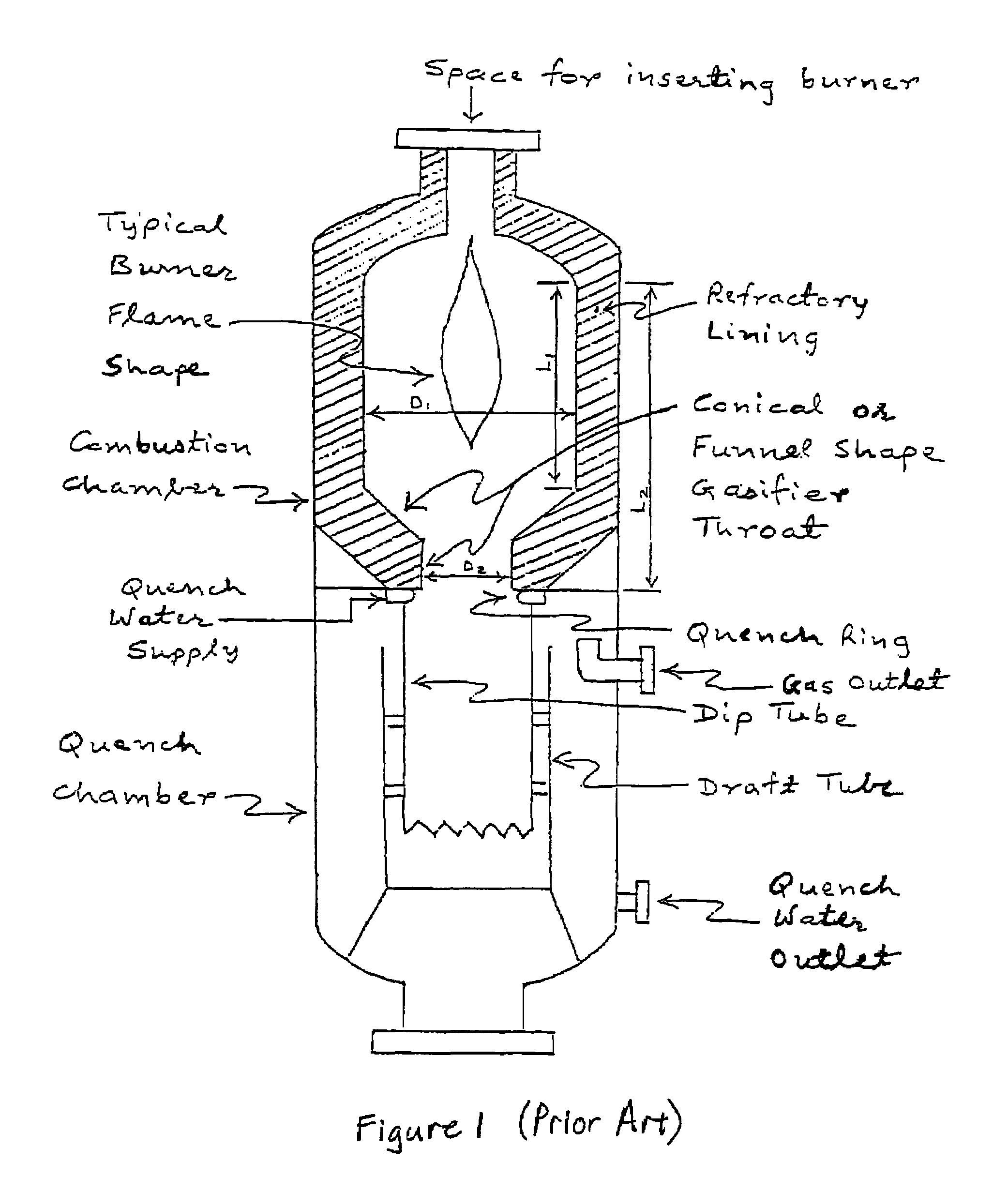
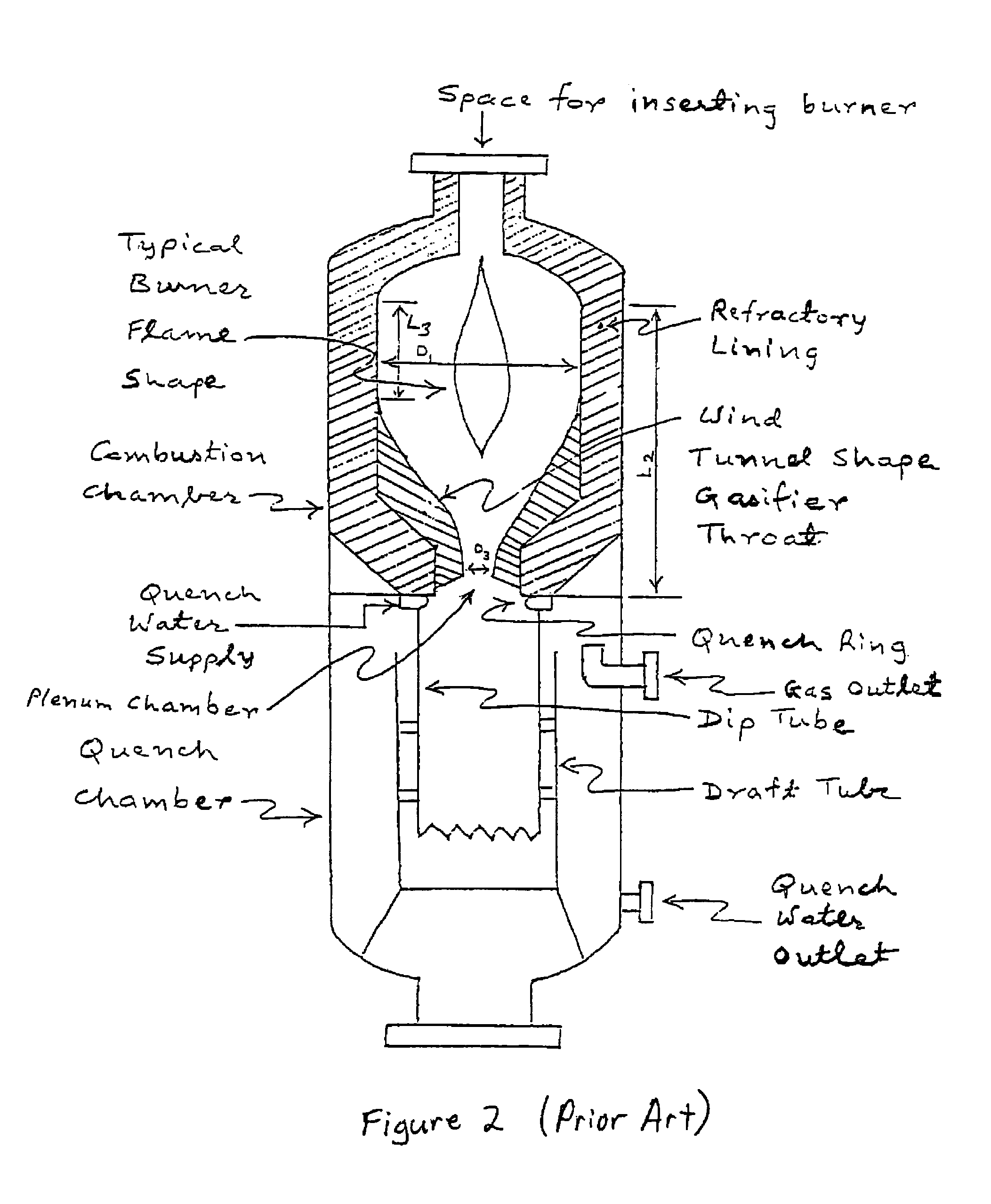
[0014]A previous patent (U.S. Pat. No. 4,574,002) suggests changing the shape of the gasifier throat to avoid ash deposits and plugs in this area. The wind tunnel shape proposed in U.S. Pat. No. 4,574,002 is shown in FIG. 2. The combustion chamber again has an external longitudinal length L2 and an internal diameter D1. However, the modified gasifier throat causes the internal longitudinal length L3 to decrease compared to the length L1 of FIG. 1. Additionally, the modified gasifier throat has an internal diameter D3. This shape provides a better chance of avoiding deposits and plugs in the throat area than the shape shown in FIG. 1. However, the wind tunnel shape is also susceptible to deposits and plugs particularly when feedstock contains metals or metal compounds that solidify at temperatures lower than 3000° F. due to the distance of the throat from the burner and its proximity to the quench ring component of the gasifier.

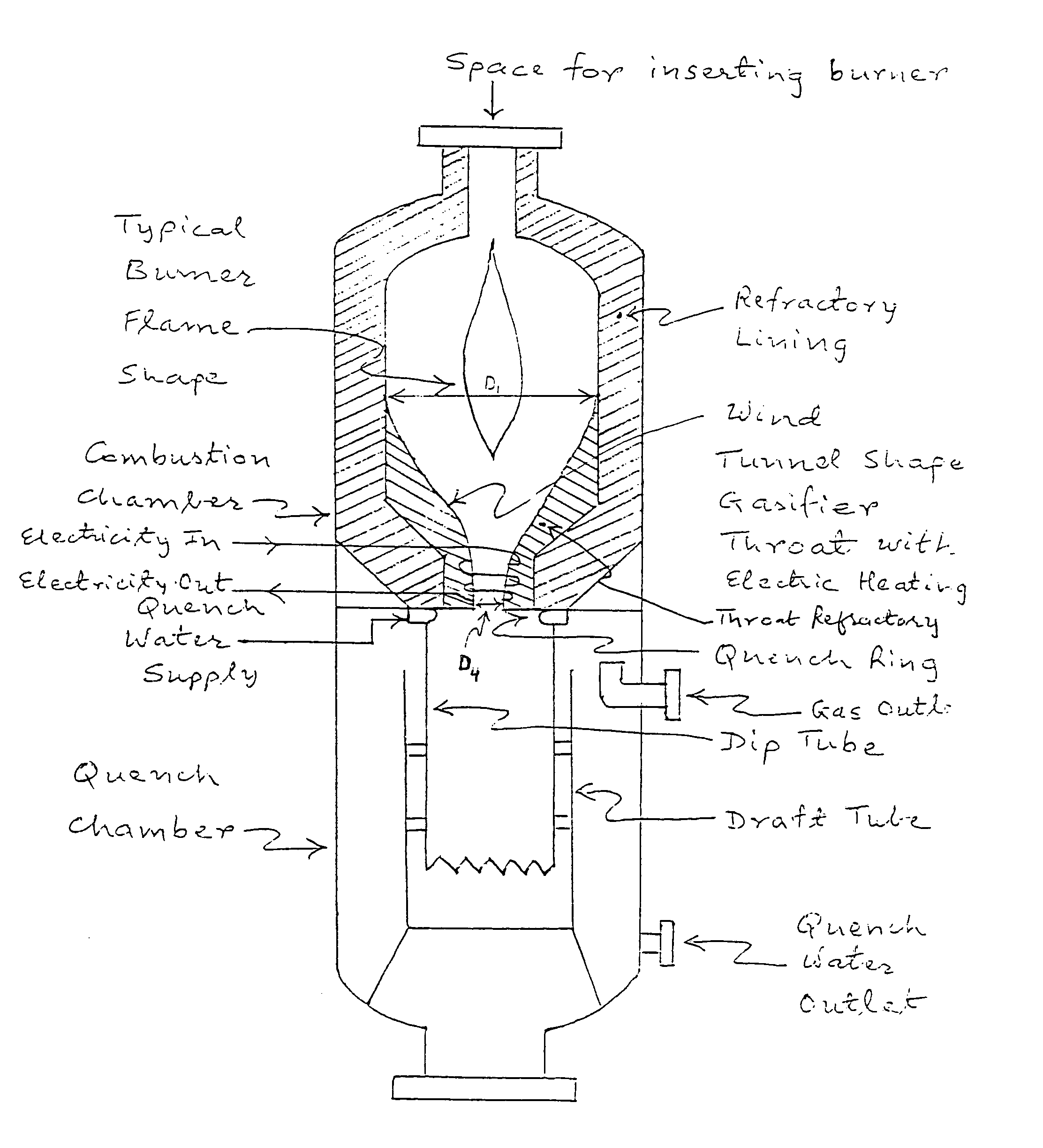
[0015]In order to avoid ash deposits and plugs in the th...


PUM

PropertyMeasurementUnit
temperatureaaaaaaaaaa
temperaturesaaaaaaaaaa

Abstract

A new combustion chamber design for a quench gasifier. Electrical heating is used in the throat area of the combustion chamber to achieve temperatures up to 3500° F. to melt ash deposits and to increase carbon conversion (reduce soot production). Silicon carbide and / or silicon nitride refractory materials are used in the hot face of the throat to withstand high temperatures and high temperature shocks. The proposed design reduces the capital cost of a gasification plant by eliminating the need for soot recovery and recycle system. This design also reduces the operating cost of the gasification plant by decreasing the frequent refractory damages that have been experienced in the throat area of the existing quench gasifiers.

Description

CROSS-REFERENCE TO RELATED PATENT APPLICATIONS[0001]The present application claims the benefit of U.S. Provisional Application Ser. No. 60 / 162,959, filed Nov. 2, 1999, entitled Combustion Chamber Design for a Quench Gasifier, which is hereby incorporated herein by reference.STATEMENT REGARDING FEDERALLY SPONSORED RESEARCH OR DEVELOPMENT[0002]Not applicable.REFERENCE TO A MICROFICHE APPENDIX[0003]Not applicable.BACKGROUND OF THE INVENTION[0004]Quench gasifiers are used to gasify ash containing hydrocarbon feedstocks such as residual oils, waste lubrication oils, petroleum cokes and coal. A typical quench gasifier design is shown in FIG. 1 (Reference: U.S. Pat. No. 4,828,579). The feedstock, the oxidant and a temperature moderator (either steam or carbon dioxide) are injected into the top portion of the gasifier through a burner and are mixed with one another in the reaction zone below the burner. Steam and carbon dioxide (CO2) moderate the temperatures in the reaction zone and also a...

Claims


Application Information

Patent Timeline
Patent Type & Authority Patents(United States)
IPC IPC(8): C10J3/00
CPCC10J3/485C10J3/523C10J3/845C10K1/101C10K1/04C10J2300/1634C10J2200/09
Inventor BAROT, DEVENDRA T.
Owner BAROT DEVENDRA T
Why Eureka
Try Eureka