Electrolytic cell for producing charged anode water suitable for surface cleaning or treatment, and method for producing the same and use of the same

a technology of electrolysis and charged anodes, which is applied in the direction of water/sewage treatment by oxidation, manufacturing tools, separation processes, etc., can solve the problems of vanionic contaminants on the surface being likely to dissolve, and achieve the effects of improving surface cleaning or treatment performance, efficient production of charged water, and improving the production efficiency of charged water

Inactive Publication Date: 2006-08-15
SONOMA PHARMA INC
View PDF347 Cites 79 Cited by
  • Summary
  • Abstract
  • Description
  • Claims
  • Application Information

AI Technical Summary

Benefits of technology

[0021]Some contaminants are adhered to the surface of the device mentioned above by electrostatic or ionic attractive forces as schematically shown in FIG. 3, where (A) indicates the contaminated surface and (B) indicates the cleaned surface: the surface of substrate is supposed to be positively charged and contaminants are supposed to be negatively charged. When the contaminated substance is immersed in the effectively charged anode water, the negatively charges on the contaminants surface reacts with excess hydrogen ions in the anode water. Thus the surface charges are partly neutralized to reduce the bonding forces and thereby to facilitate cleaning. Conversely, when the contaminants are positively charged, the negative charges on the contaminated substance surface disappear to reduce the bonding forces. On the other hand, in the case of ionic contaminants, when the contaminated substance is immersed in anode water with excessive hydrogen ions, the anionic contaminants on the surface are likely to dissolve and then migrate to the anode solution to cancel the excessive charge. Using electrolytic water increases thus cleaning efficacy.
[0025]The inventors of this invention have found that it is important to pass water not only over the back side of electrode but also over the front side of electrode, based on the study to improve charged water production efficacy.
[0026]This result has led to the development of new methods for improving surface cleaning or treatment performance in semiconductors, glass, resins or the like, and of the apparatus (electrolytic cell) of the present invention which can efficiently produce the charged water with an excellent performance described above.
[0030]The term “surface cleaning” used in this specification means an operation to remove contaminants from the surface and “surface treatment” means an operation to change surface composition or the like of a substance, e.g., glass, having ions, e.g., Na+, K+, and H+, bonded in the bonding network of Si—O. Phenomena of the migration of Na+ ions in glass were observed. When Na+ ions present in the vicinity of the surface are removed, or more specifically ion-exchanged on the surface, the surface is prevented from roughing caused by the Na+ ions. This process means the surface treatment, which is different form, the removal of foreign particles or impurity ions form the surface.
[0048]These factors greatly depend on the electrode hole structure and ion-exchange resin size: increasing opening size and / or ion-exchange resin size decreases the resistance to water flow and, at the same time, increases the effective current density because contact area between the electrode and resins decreases. However, it is difficult to hold the ion-exchange resins between the membrane and electrode, when opening size increases excessively. Therefore, there is an optimum shape for each of opening and ion-exchange resin.

Problems solved by technology

On the other hand, in the case of ionic contaminants, when the contaminated substance is immersed in anode water with excessive hydrogen ions, the anionic contaminants on the surface are likely to dissolve and then migrate to the anode solution to cancel the excessive charge.

Method used


Image

  • Electrolytic cell for producing charged anode water suitable for surface cleaning or treatment, and method for producing the same and use of the same
  • Electrolytic cell for producing charged anode water suitable for surface cleaning or treatment, and method for producing the same and use of the same
  • Electrolytic cell for producing charged anode water suitable for surface cleaning or treatment, and method for producing the same and use of the same

Examples


embodiment 1

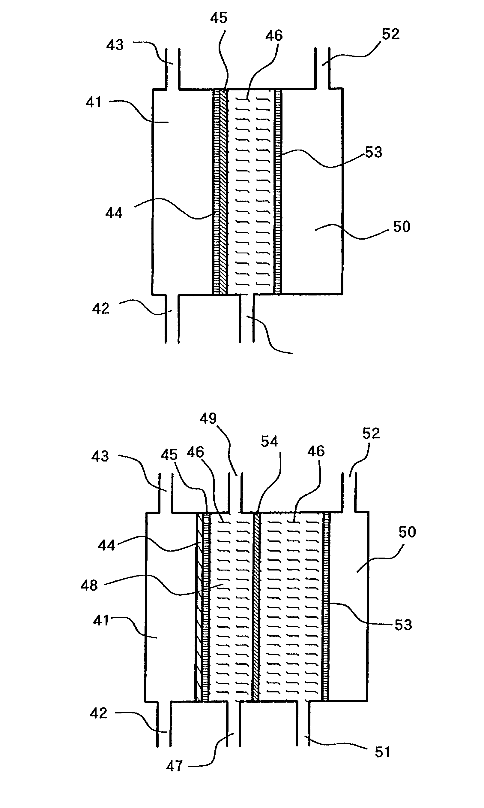
[0070]FIG. 4 illustrates the new three-chamber type electrolytic cell made by improving the conventional three-chamber cell in which the perforated electrode plate shown in the drawing is used.

[0071]The anode 53 was closely attached to the cation-exchange membrane before the improvement. Therefore, the electrolytic water flowed along the anode plane, and the electrolysis reaction proceeded between the electrode and ion exchange membrane. As a result, the electrolysis products were formed first between the electrode and ion exchange membrane, and then moved toward the backside of electrode by diffusion or the like.

[0072]In the present invention, on the other hand, the anode is perforated to provide the passages for electrolytic water passing over the electrode surface, in order to utilize the electrolysis product more efficiently. As a result, the electrolytic water flows not only on the electrode surface but also thorough the holes opened in the electrode. The relationship between o...

embodiment 2

[0076]The electrolytic cell shown in FIG. 5 has a characteristic structure in that the feed water flows into the middle chamber 46 and the electrolyzed water discharged from the anode chamber 50 is recovered as the charged anode water. The cell structure as those shown in FIG. 4 are given the same number and their descriptions is omitted.

embodiment 3

[0077]The electrolytic cell structure includes a mechanism to adjust the position of anode 53 in the current flowing direction, as shown in FIG. 6. This structure is provided with a frame, outside of the cell, which holds the mobile anode position-adjusting mechanism.

[0078]The anode position adjusting mechanism typically is composed of an anode-supporting rod provided with a screw, by which the anode position can be adjusted.

[0079]The structure is described in more detail. This structure makes it possible to adjust position of the anode 53, shown in FIG. 4 for embodiment 1, in the current passing direction. More specifically, the anode-supporting rod 58 is set at approximately center of the anode 53 in the current passing direction, held by the holding frame 57 provided in the anode chamber 50 in such a way to be movable in the axial direction, and screwed into the position-adjusting mechanism 56, provided outside of cell, via the O-ring 55 which seals the anode-supporting rod 58. T...


PUM

PropertyMeasurementUnit
reduction potentialaaaaaaaaaa
temperatureaaaaaaaaaa

Abstract

The present invention provides an electrolytic cell, which can efficiently produce, charged water having an excellent performance of improving surface cleaning or treatment of an object, e.g., semiconductor, glass, or resin and of cleaning and sterilizing medical device.The electrolytic cell of the present invention is for producing charged anode water suitable for surface cleaning or treatment, including the cathode chamber 41 and anode chamber 50, fluorinated cation-exchange membrane 46 provided to separated these chambers from each other, cathode 44 closely attaché to the cation-exchange membrane 45 on the side facing the cathode chamber 41, and middle chamber 48 filled with the cation-exchange resin 46, provided on the other side of The cation-exchange membrane 46, the cation-exchange resin 46 being arranged in such a way to come into contact with the fluorinated cation-exchange membrane 45, wherein the feed water is passed into the middle chamber 48 and passed thorough The anode chamber 50 to be recovered as the charged anode water.

Description

BACKGROUND OF THE INVENTION[0001]1. Field of the Invention[0002]The present invention is related to a method for surface cleaning or treatment of semiconductors, glass, or resins, and device for producing electrically charged water as utility water for the above methods, more particularly a technique for providing an electrolysis cell, which can produce electrically charged water suitable for surface cleaning or treatment without using chemical in consideration of environmental protection. The electrically charged water produced by using the electrolysis cell also has antimicrobial activates, and is suitable for cleaning and sterilizing medical devices for which high cleanliness is required.[0003]2. Description of the Related Art[0004]Electrolysis cell using ion exchange membrane, as shown FIG. 1, facilitates the electrolysis of water with low conductivity such as RO water treated using a reverse osmosis membrane pure water, and ultra pure water. In this cell, a fluorinated cation e...

Claims


Application Information

Patent Timeline
Patent Type & Authority Patents(United States)
IPC IPC(8): C25B9/12C02F1/461C25B1/00A61L2/02A61L2/03A61L2/18A61L2/20C02F1/42C02F1/46C02F1/469C02F1/78C25B9/23
CPCA61L2/035A61L2/202C02F1/4618A61L2/183C02F2303/04A61L2202/24C02F1/46109C02F1/469C02F1/78C02F2001/425C02F2001/46123C02F2001/46161C02F2001/46185C02F2201/46115C02F2201/46155C02F2201/46195C02F2209/04
Inventor SUMITA, OSAO
Owner SONOMA PHARMA INC
Why Eureka
Try Eureka