Transmission apparatus using a plastic fiber

a technology of transmission apparatus and plastic fiber, which is applied in the direction of optical elements, radio frequency control devices, instruments, etc., can solve the problems of obstructing the popularization of fibers, difficult to perform fiber laying operations under ordinary environmental conditions, and obstructing the propagation of fibers, etc., to achieve the effect of high light receiving efficiency and quick response characteristics

Inactive Publication Date: 2006-09-12
FUJIFILM CORP +1
View PDF7 Cites 5 Cited by
  • Summary
  • Abstract
  • Description
  • Claims
  • Application Information

AI Technical Summary

Benefits of technology

[0010]The primary object of the present invention is to provide a transmission apparatus comprising a combination of a plastic fiber, which is capable of forming a large-diameter cor...

Problems solved by technology

Therefore, fiber laying operations under ordinary environmental conditions, such as conditions at construction work sites, are not easy to perform.
The difficulty of the fiber laying operations obstructs further popularization of the fibers described above.
Therefore, in cases where a successively pulsed light signal as illustrated in FIG. 9A is inputted into the step index type of fiber and transmitted through the step index type of fiber, the problems occur in that, as illustrated in FIG. 9B, the pulses, which are adjacent to each other on the time axis, overlap one upon the other, and a perfectly extinct state cannot be obtained with respect to a logic “0” level of th...

Method used


Image

  • Transmission apparatus using a plastic fiber
  • Transmission apparatus using a plastic fiber
  • Transmission apparatus using a plastic fiber

Examples


first embodiment

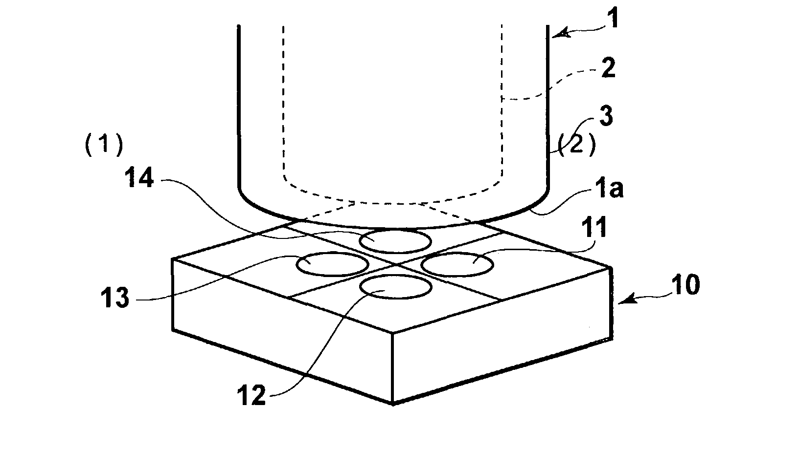
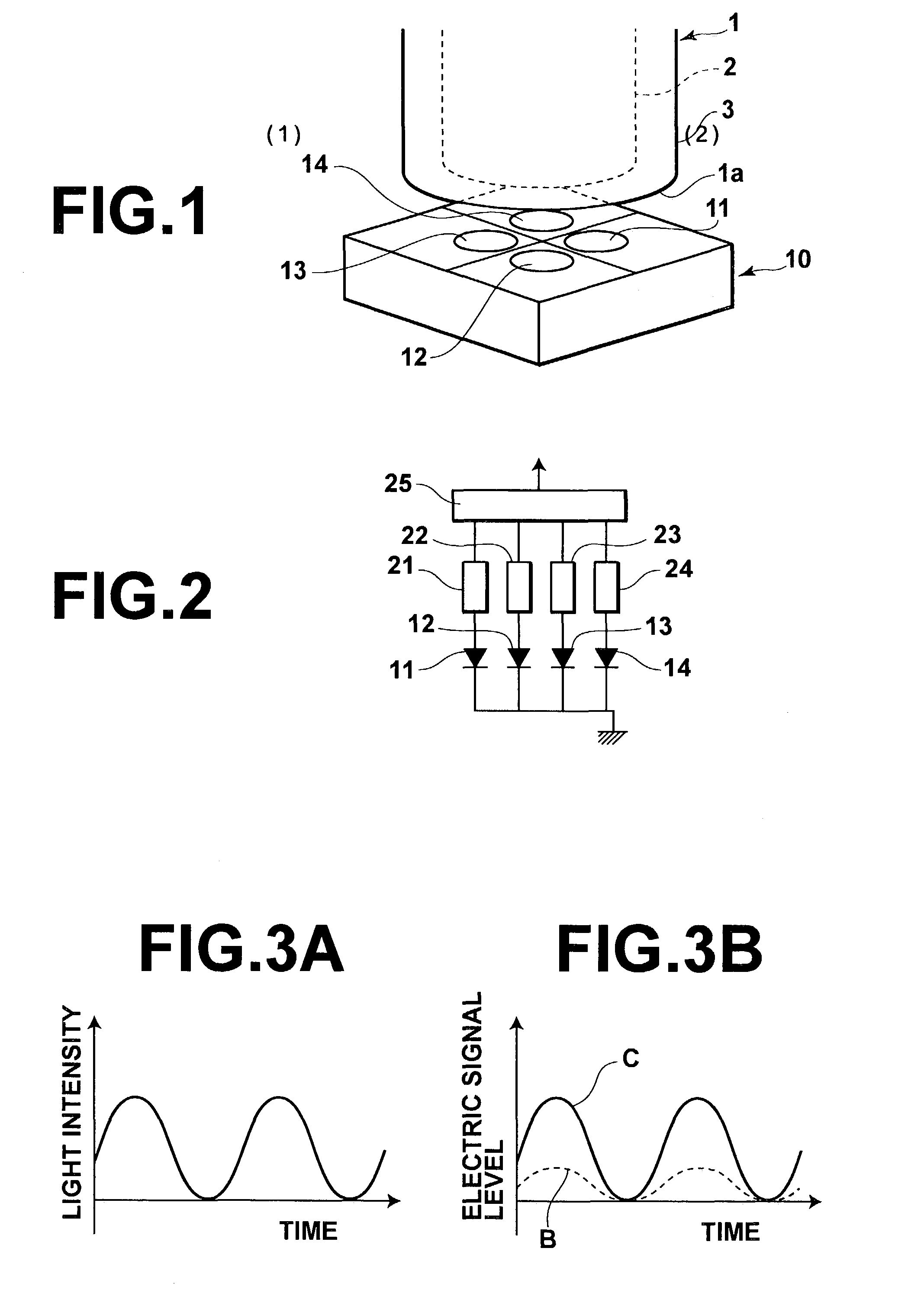
[0040]Specifically, for example, a successively pulsed light signal, which has a wave form as illustrated in FIG. 3A, may be inputted into the plastic fiber 1. In such cases, a light detection signal, which is obtained from the amplification of the output of each of the semiconductor light receiving devices 11, 12, 13, and 14 performed by the corresponding one of the pre-amplifiers 21, 22, 23, and 24, has a wave form B illustrated in FIG. 3B. Also, a light detection signal, which is obtained from the amplification of the total sum of the pre-amplified light detection signals of the semiconductor light receiving devices 11, 12, 13, and 14, the amplification being performed by the amplifier 25, has a wave form C illustrated in FIG. 3B and thus has a high level. Also, as described above, quick response is capable of being achieved. Therefore, the light detection signal formed by the amplifier 25 is capable of being obtained such that the logic “0” level of the light detection signal is...

second embodiment

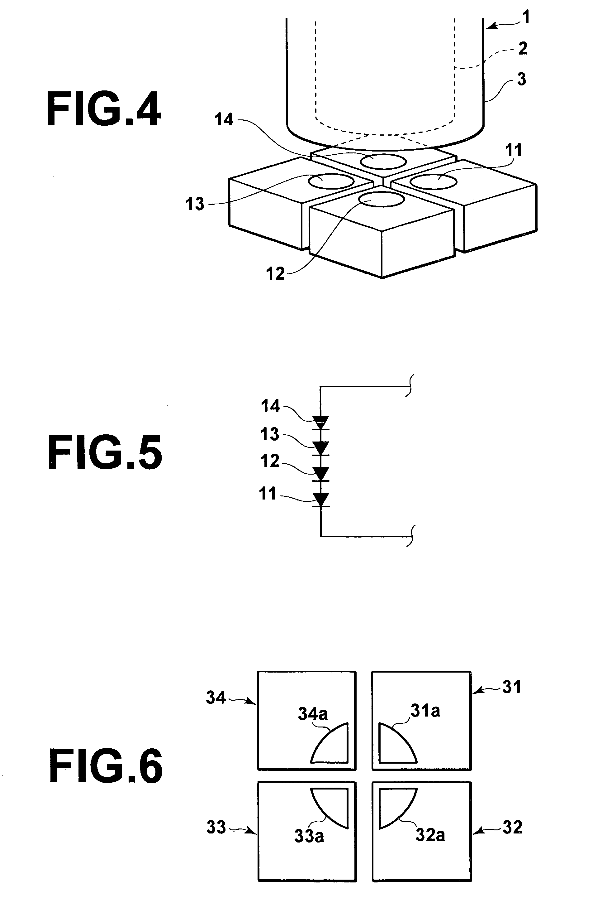
[0044]FIG. 5 is a circuit diagram showing an electric circuit of the transmission apparatus of FIG. 4. As illustrated in FIG. 5, in the second embodiment, the semiconductor light receiving devices 11, 12, 13, and 14 are connected in series. In such cases, since the light receiving area of each of the semiconductor light receiving devices 11, 12, 13, and 14 is small, quick response is capable of being achieved. Also, the light signal having been propagated through the plastic fiber 1 is capable of being detected by the group of the four semiconductor light receiving devices 11, 12, 13, and 14. Therefore, the light receiving efficiency is capable of being kept high.

[0045]In the first and second embodiments described above, each of the light receiving sections of the semiconductor light receiving devices has the circular shape. Alternatively, each of the light receiving sections of the semiconductor light receiving devices may have an asymmetric shape. For example, as illustrated in FI...


PUM


Abstract

A transmission apparatus comprises a plastic fiber, and a photodetector for detecting light, which has been propagated through the plastic fiber. The photodetector comprises a plurality of semiconductor light receiving devices, whose light receiving sensitivity wavelength regions are identical with one another, each of the semiconductor light receiving devices having a light receiving area smaller than a cross-sectional area of a core of the plastic fiber. The transmission apparatus is capable of achieving both a high light receiving efficiency and quick response characteristics.

Description

BACKGROUND OF THE INVENTION[0001]1. Field of the Invention[0002]This invention relates to a transmission apparatus, which utilizes a plastic fiber, for use in an optical communication system, and the like.[0003]2. Description of the Related Art[0004]Ordinarily, as light propagation paths in optical communication, single mode fibers or multi-mode fibers containing quartz glass as a principal material are utilized. The single mode fibers or the multi-mode fibers containing quartz glass as a principal material have a diameter of at most 200 μm. In alignment processes for the fibers, a high position matching accuracy on the order of micron is required. Therefore, fiber laying operations under ordinary environmental conditions, such as conditions at construction work sites, are not easy to perform. The difficulty of the fiber laying operations obstructs further popularization of the fibers described above.[0005]Recently, plastic fibers, which have a comparatively large diameter and are c...

Claims


Application Information

Patent Timeline
IPC IPC(8): G02B6/42G02B6/43H01L27/144H01L27/14H01L31/0232H04B10/2507H04B10/2581H04B10/40H04B10/50H04B10/60H04B10/67
CPCH04B10/2581G02B6/43
Inventor MATSUMOTO, KENJIHAYAKAWA, TOSHIRO
Owner FUJIFILM CORP
Why Eureka
Try Eureka