Teletext data separation apparatus

a technology of teletext data and separation apparatus, which is applied in the direction of plural information simultaneous broadcast, signal generator with optical-mechanical scanning, television system, etc., can solve the problems of increasing current consumption or spurious emission of processing circuit, unable to achieve an appropriate level, and unable to generate satisfactory slice levels, etc., to reduce the adverse effect of power supply noise, reliable separation of teletext data, and improved conversion accuracy of a/d converter

Inactive Publication Date: 2006-09-19
RENESAS TECH CORP +1
View PDF13 Cites 9 Cited by
  • Summary
  • Abstract
  • Description
  • Claims
  • Application Information

AI Technical Summary

Benefits of technology

[0026]The present invention is implemented to solve the foregoing problems. It is therefore an object of the present invention to provide a teletext data separation apparatus capable of generating an appropriate slice level enabling the reliable separation of the teletext data even when the video signal suffers from noise or distortion because of the adverse effect of the weak electric field, ghost or the like.
[0027]Another object of the present invention is to provide a teletext data separation apparatus capable of generating an appropriate slice level by improving the conversion accuracy of the A / D converter for sampling the teletext data by reducing the adverse effect of the noise of the power supply.
[0028]Still another object of the present invention is to provide a teletext data separation apparatus capable of generating an appropriate slice level by increasing the flexibility in separating the digital data, which is obtained by sampling the teletext data, and required for generating the slice level.
[0029]According to one aspect of the present invention, there is provided a teletext data separation apparatus including a register for setting by its register value the number of sampling points of an adder and a divider for determining the slice level; and means for varying the register value of the register in response to a reception state to increase the predetermined number of the sampling points (16 points). Thus, it offers an advantage of being able to optimize the slice level for separating the teletext data even if the reception conditions of the composite video signal fall into bad conditions such as weak electric field or ghost.

Problems solved by technology

Although an increasing number of the sampling points will be able to improve the slice characteristic, it will increase the current consumption or spurious emission of the processing circuit.
However, generating the slice level from the 16-point sampled data for separating the teletext data has the following problems.
First, it cannot achieve an appropriate level when the reception is made under a bad condition such as a weak electric field or ghost.
Second, although the conventional circuit generates the slice level during the initial two clock pulses of the clock run-in signal of FIG. 10, it has a problem in that it cannot generate a satisfactory slice level in a bad condition.
This is because the number of clock pulses of the clock run-in signal can vary from that of the normal case, or it can become an irregular signal with insufficient peak value or waveform.
Third, it has a problem in that the volume of software grows heavier with the processing speed because of the following reason.
However, when the microcomputer operates, its noise is usually superimposed on its power, which offers a problem of having an adverse effect on the power supply of the A / D converter 150, thereby degrading its conversion accuracy.

Method used


Image

  • Teletext data separation apparatus
  • Teletext data separation apparatus
  • Teletext data separation apparatus

Examples


embodiment 1

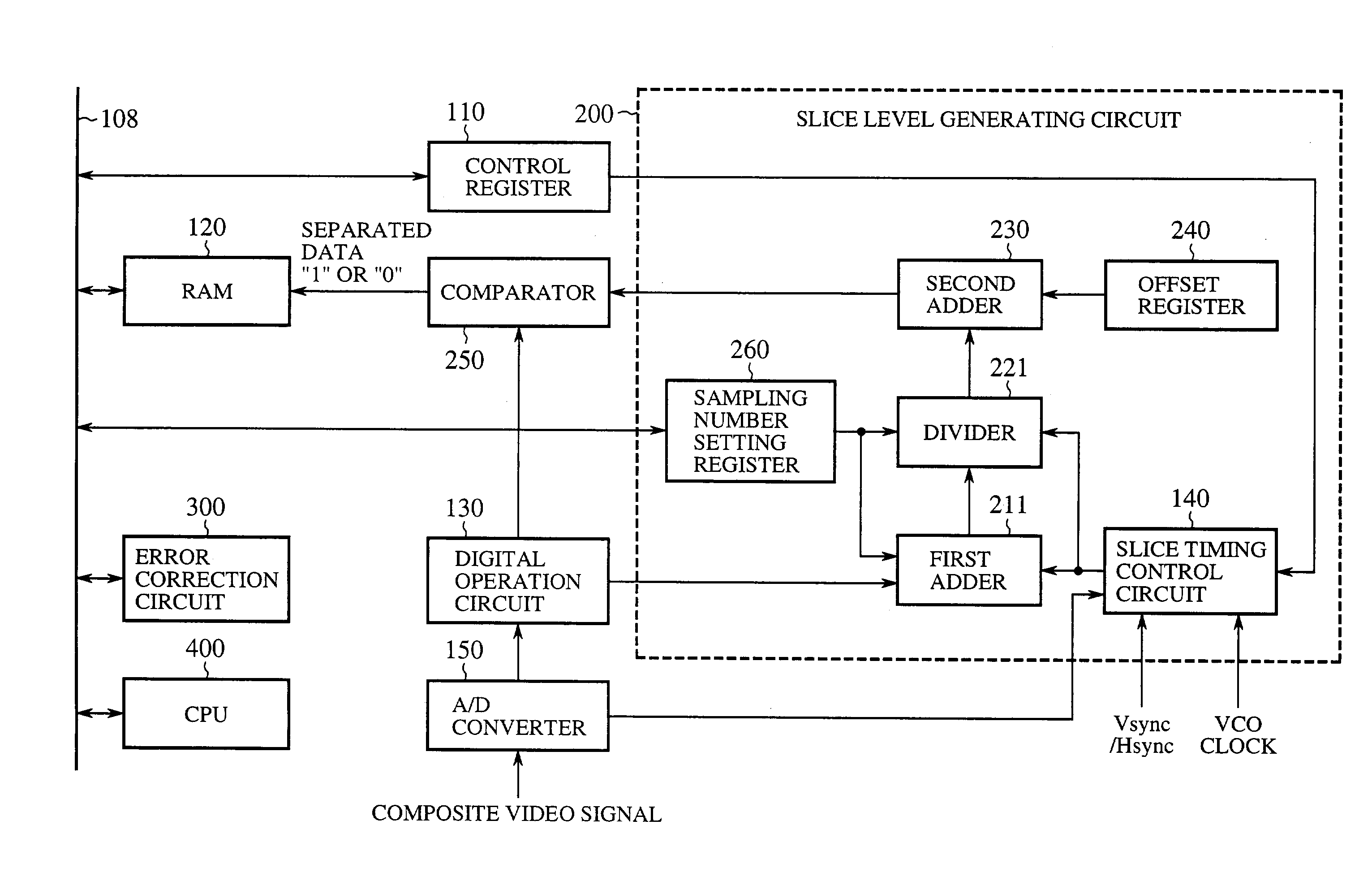
[0046]FIG. 1 is a block diagram showing a configuration of an embodiment 1 of the teletext data separation apparatus in accordance with the present invention. In FIG. 1 the same reference numerals as those of FIG. 14 designate the same portions, and the description thereof is omitted as a rule. In FIG. 1, the reference numeral 111 designates a control register, 211 designates a first adder, 221 designates a divider, 300 designates an error correction circuit, and 400 designates a CPU.

[0047]As described before, the conventional circuit uses 16 sampling points to generate the slice level. In contrast with this, the present embodiment 1 generates the slice level as follows.

[0048]The control register 111 includes bits for changing the number of the sampling points. The RAM 120 stores the slice data that includes a Hamming code or parity bits for the error correction. The slice data is once read by the CPU 400 via a bus 108, and undergoes the identification of the data, the parity check,...

embodiment 2

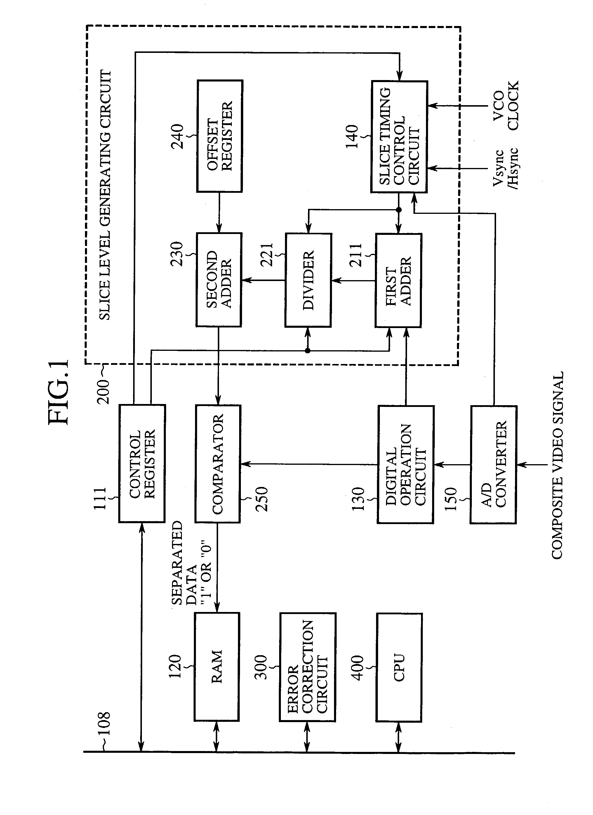
[0052]FIG. 2 is a block diagram showing a configuration of an embodiment 2 of the teletext data separation apparatus in accordance with the present invention. In FIG. 2, the same or like portions to those of FIG. 1 are designated by the same reference numerals, and the description thereof is omitted as a rule. The reference numeral 110 designates a control register, and 260 designates a sampling number setting register for setting the number of the sampling points of the first adder 211 and divider 221.

[0053]The present embodiment 2 includes the sampling number setting register 260 to control the operation of the first adder 211 and divider 221 so that the number of the sampling points can be varied in response to the reception state as described in the foregoing embodiment 1. Thus, the general operation equations of the first adder 211 and divider 221 are given by the following equations.

F(a)′=a1+a2+ . . . +an

G(x′)′=x′ / n

where n is the value set by the sampling number setting regist...

embodiment 3

[0055]FIG. 3 is a block diagram showing a configuration of an embodiment 3 of the teletext data separation apparatus in accordance with the present invention. In FIG. 3, the same or like portions to those of FIG. 2 are designated by the same reference numerals, and the description thereof is omitted as a rule. In FIG. 3, the reference numeral 270 designates an operation starting position setting register.

[0056]In the bad reception conditions, the number of the clock pulses can vary, and an irregular signal with insufficient peak value or waveform can occur. Since the positions of the sampling points for the slice level are located in the initial two clock pulse portion of the clock run-in signal, the irregular waveform lacking this portion will disable the generation of the appropriate slice level. Considering this, the present embodiment 3 carries out the following operation.

[0057]The operation starting position setting register 270 instructs the slice timing control circuit 140, w...


PUM


Abstract

A teletext data separation apparatus has a slice level generating circuit including a slice timing control circuit, a control register, an adder and a divider. The slice timing control circuit generates a timing signal for sampling. The control register carries out ON / OFF control of the slice timing control circuit. The control register sets by its register value the number of the sampling points of the adder and divider. By varying the register value in response to the reception state, the number of the sampling points can be increased from the specified 16 points, for example. This makes it possible for teletext data separation apparatus to generate an appropriate slice level that enables the teletext data to be separated reliably even in conditions where noise or distortion occurs in the video signal because of the effect of a weak electric field or ghost.

Description

BACKGROUND OF THE INVENTION[0001]1. Field of the Invention[0002]The present invention relates to a teletext data separation apparatus for separating superimposed teletext data from a composite video signal decoded by a receiver of a television broadcast.[0003]2. Description of Related Art[0004]Today, the television broadcasts have spread widely throughout the world, and individual homes can enjoy video information transmitted by terrestrial broadcasting, cable broadcasting or satellite broadcasting by receiving it by TV receivers. In addition, teletext services become available which provide text information superimposed on a composite video signal of ordinary television broadcasts. The teletext services, which offer text information as well as graphics on the TV screens, provide various services according to the difference of transmission standards. For example, Japan has propagated teletext (ADAMS), the U.S. has propagated CCD (Closed Caption Decoder) and Europe and Southeast Asia...

Claims


Application Information

Patent Timeline
Patent Type & Authority Patents(United States)
IPC IPC(8): H04N11/00H04N7/00H04N7/025H04H20/00H04H20/28H04H40/18H04N7/03H04N7/035H04N7/088
CPCH04H20/28H04N7/0882H04N7/0355H04H40/18
Inventor MATSUMOTO, SEIJI
Owner RENESAS TECH CORP
Why Eureka
Try Eureka