Motor control apparatus

a technology of motor control and control module, which is applied in the direction of electric motor control, emergency protective circuit arrangement, light and heating apparatus, etc., can solve the problems of time delay in stopping the output of adverse effect of heat on the cooling function of the engine, and damage to the semiconductor switch device in the pwm control module, etc., to achieve high reliability

Active Publication Date: 2006-09-26
DENSO CORP
View PDF6 Cites 67 Cited by
  • Summary
  • Abstract
  • Description
  • Claims
  • Application Information

AI Technical Summary

Benefits of technology

[0009]It is thus an object of the present invention addressing the above problems to provide a motor control apparatus for controlling a motor as an apparatus capable of carrying out an operation to protect the apparatus itself and the motor from damage caused by heat generated by an excessively large current with a high degree of reliability when the excessively large current flows while maintaining the operating state of the motor.

Problems solved by technology

When an excessively large current flows due to a rotation lock state of the fan motor or a short circuit, it is quite likely that a semiconductor switch device in the PWM control module is damaged by heat.
When the semiconductor switch device is put in a state of being turned off continuously as it is after detection of the flow of the excessively large current, however, the fan motor is also put in a stopped rotation state as it is, having an adverse effect on the function to cool the engine.
Since the current conduction through the fan motor is continued, however, it is quite likely that a layer short circuit is generated in the fan motor eventually in dependence on the location of the cause of the excessively large current.
Thus, in particular, a time delay unavoidably occurs in an operation to stop the output of the PWM control module when the temperature of the inside of the PWM control module exceeds the upper limit.
When such a time delay occurs, the temperature of the inside of the PWM control module most likely increases sharply due to a layer short circuit generated in the fan motor or another cause.
An inability to cope with such a sharp increase in temperature will lower reliability of the operation to protect the motor control apparatus and the motor from damage.

Method used


Image

  • Motor control apparatus
  • Motor control apparatus
  • Motor control apparatus

Examples


first embodiment

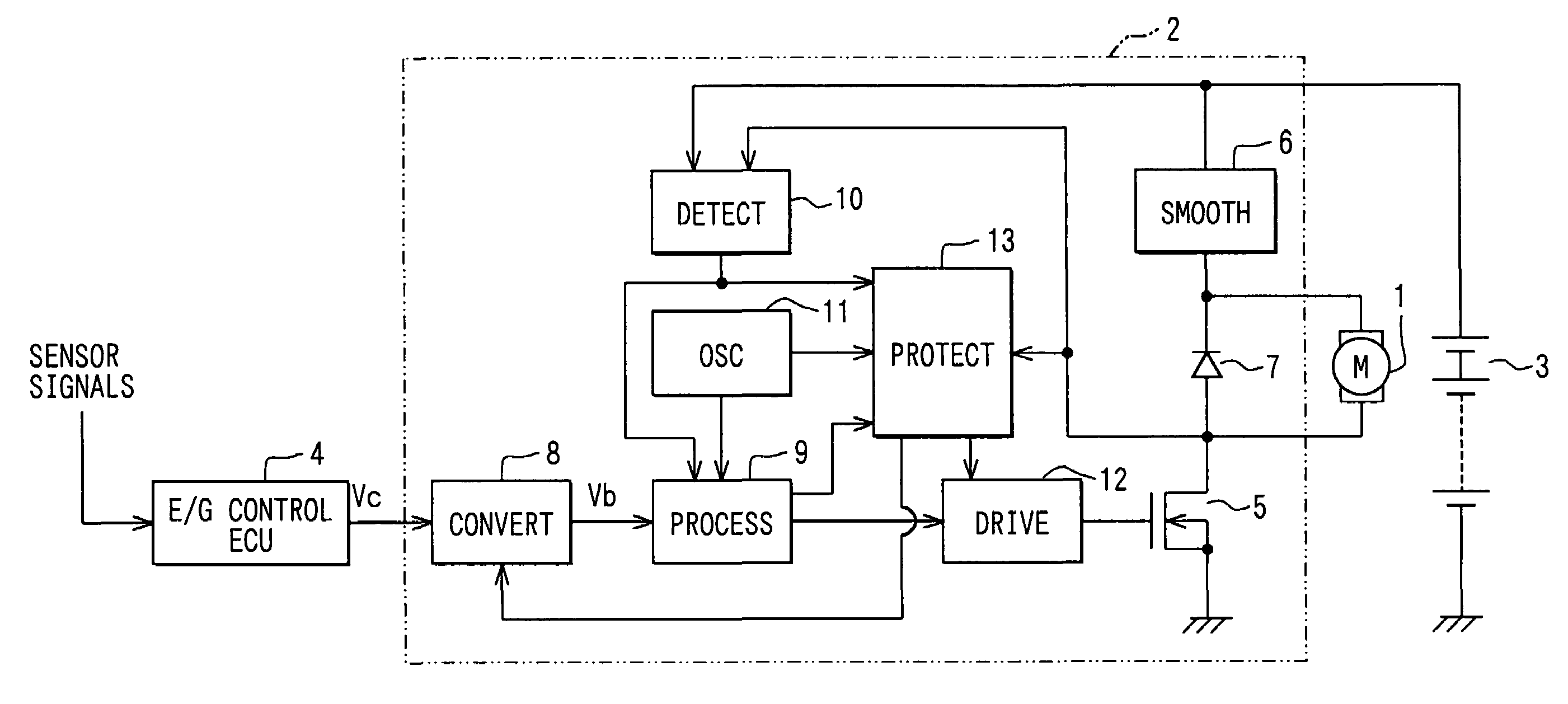
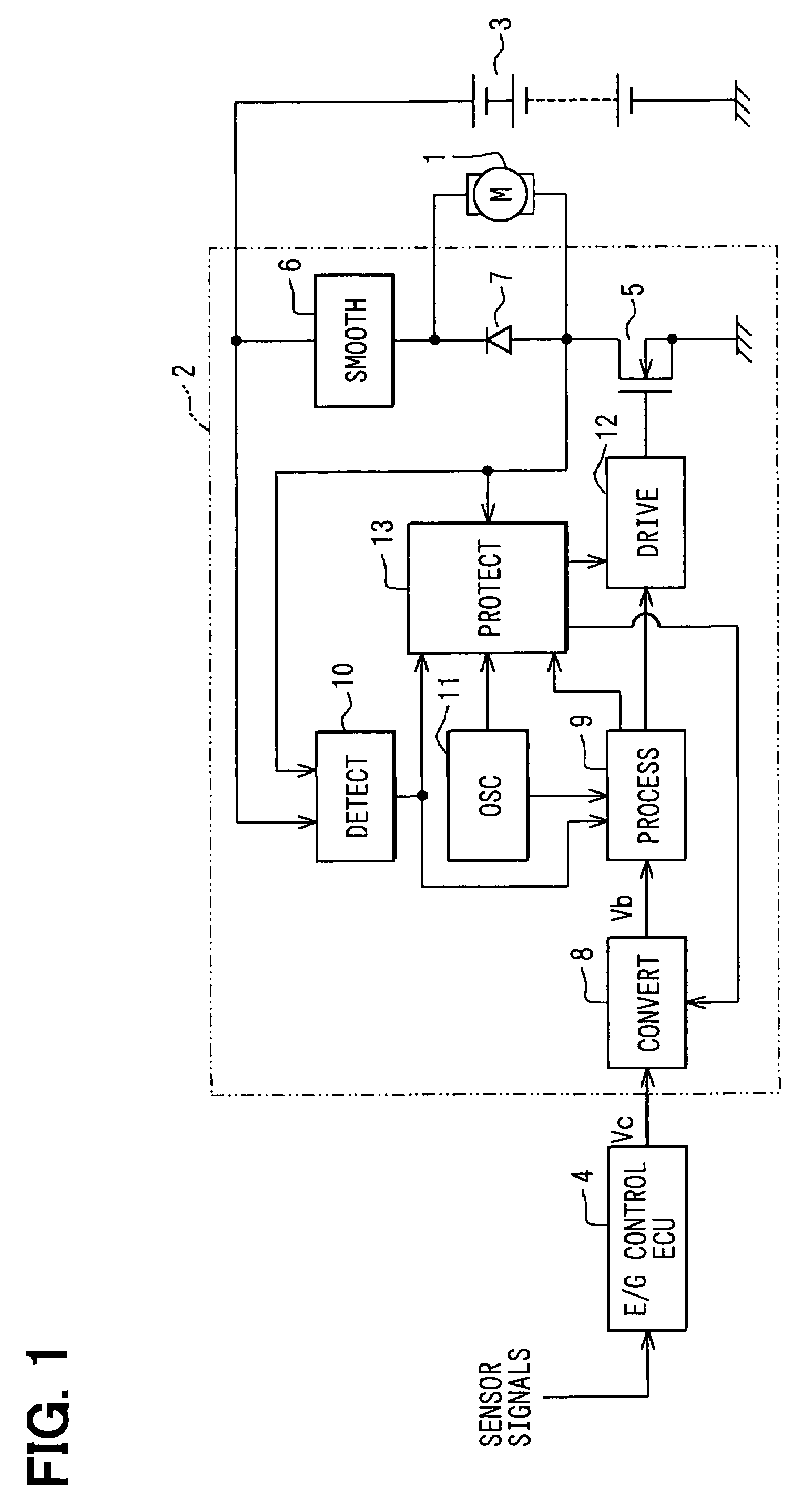
[0024]Referring to FIG. 1, a direct current motor 1 serves as a driver of a blower fan (not shown) for cooling down engine cooling refrigerant flowing through the inside of a heat exchanger such as a radiator. A motor control apparatus 2 controls the rotating speed of a motor 1. A battery 3 supplies power to the motor control apparatus 2 by way of an ignition switch (not shown). It is to be noted that, in some configurations, the battery 3 supplies power to the motor control apparatus 2 directly.

[0025]The voltage applied to the motor 1 determines the rotating speed of the blower fan. The motor control apparatus 2 adjusts the level of the voltage by adoption of a pulse width modulation (PWM) control method of switching application of the output of the battery 3 to the motor 1. The motor control apparatus 2 has a configuration of receiving a voltage command signal Vc from an electronic control unit (ECU) 4 for an engine (E / G) control. The voltage command signal Vc is an output level c...

first embodiments

Modification of First Embodiments

[0091]The first embodiment can be modified as follows.

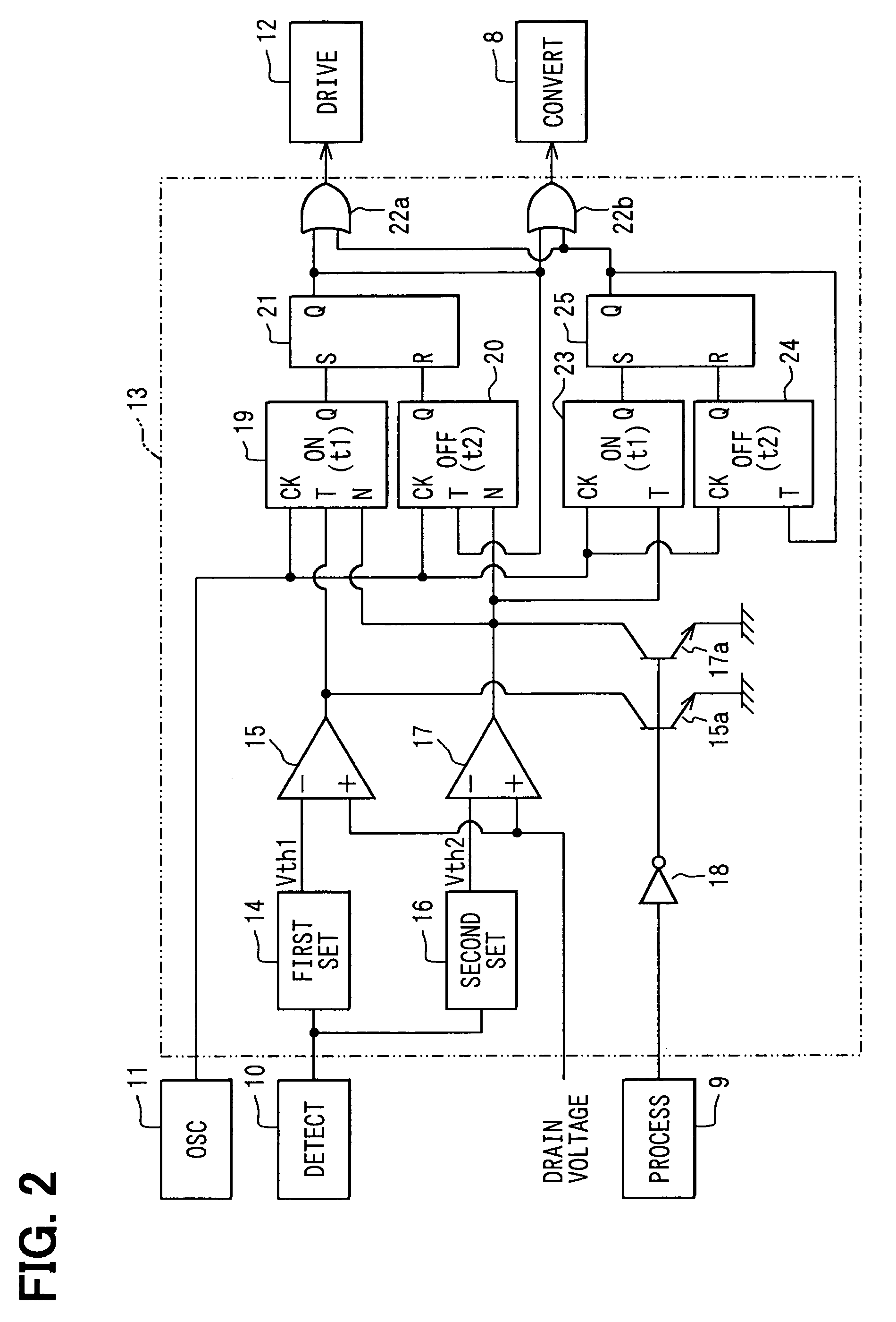
[0092]While the first embodiment has only 2 stages of combinations of an ON-timer and an OFF-timer, that is, the combination of the first ON-timer 19 and the first OFF-timer 20 as well as the combination of the second ON-timer 23 and the second OFF-timer 24, the number of such combination stages can also be increased to 3 or even a larger value. In a configuration including a larger number of such stages, the over-current protection operation can be carried out with higher accuracy in dependence on the magnitude of the motor current IM.

[0093]In addition, the timer operating ON time period t1 set in the first ON-timer 19 is set at a value greater than the timer operating ON time period t1′ set in the second ON-timer 23 to satisfy a relation of t1>t1′. On the other hand, the timer operating OFF time period t2 set in the first OFF-timer 20 is set at a value greater than the timer operating OFF time p...

second embodiment

[0095]The second embodiment shown in FIG. 6 is basically the same as the first embodiment shown in FIG. 1. In the second embodiment, however, a resistor 100 is connected between the negative side terminal of the motor 1 and a junction point between the MOSFET 5 and the flywheel diode 7. In addition, a voltage appearing between the ends of the resistor 100 is supplied to the over-current protection circuit 13.

[0096]In the over-current protection circuit 13 shown in FIG. 7, the motor current IM is detected as a current voltage (S3 in FIG. 8) appearing between the ends of the resistor 100. The over-current protection circuit 13 includes a low side over-current detection threshold voltage setting circuit 140 for setting a low side over-current detection threshold voltage Va (S1 in FIG. 8) corresponding to a low side threshold current. A low side determination comparator 150 compares the low side over-current detection threshold voltage Va output by the low side over-current detection th...


PUM


Abstract

In a control apparatus for a motor, an over-current protection circuit detects an abnormality in a motor current forcibly turns off a MOSFET. The over-current protection circuit has a timer function and a time switching function. In the timer operation, the over-current protection circuit stops an abnormality detection signal for an ON time period before producing the signal for an OFF time period when a current flowing through the motor exceeds a predetermined threshold value. The time switching function is for controlling to lengthen the OFF time period to a relatively larger value in comparison with the ON time period.

Description

CROSS REFERENCE TO RELATED APPLICATION[0001]This application is based on and incorporates herein by reference Japanese Patent Application No. 2003-71829 filed on Mar. 17, 2003.FIELD OF THE INVENTION[0002]The present invention relates to a motor control apparatus for controlling a current of a motor by turning on and off a semiconductor switch device.BACKGROUND OF THE INVENTION[0003]In order to reduce noises and power consumption in an apparatus for controlling a fan motor used in an engine cooling system in an automobile, for example, a pulse width modulation (PWM) control module is used to execute continuous or proportional control on the rotating speed of the fan motor. When an excessively large current flows due to a rotation lock state of the fan motor or a short circuit, it is quite likely that a semiconductor switch device in the PWM control module is damaged by heat.[0004]As a general solution, an over-current protection circuit capable of coping with such an excessively larg...

Claims


Application Information

Patent Timeline
Patent Type & Authority Patents(United States)
IPC IPC(8): H02H5/04H02P7/29H02H7/08H02H7/085H02P7/291
CPCH02H7/0833H02P29/02H02H7/0858
Inventor NOMURA, MANABUYOSHIMURA, SATOSHI
Owner DENSO CORP
Why Eureka
Try Eureka