Optical transmitter and optical transmission system

a transmission system and optical transmitter technology, applied in the field of optical transmitters and optical transmission systems, can solve the problems of system performance degradation, optical output power of the modulating unit decreases, and insertion loss in the modulating unit increases, so as to facilitate the enhancement of high-speed operation the increase of the line rate of the transmission system is easy to realize, and the loss of the optical modulator is decreased.

Active Publication Date: 2006-10-03
NIPPON TELEGRAPH & TELEPHONE CORP
View PDF16 Cites 33 Cited by
  • Summary
  • Abstract
  • Description
  • Claims
  • Application Information

AI Technical Summary

Benefits of technology

[0041]In addition, as yet another embodiment of the transmitter and the pre-coding device in the optical transmission system according to the present invention, by using a structure comprising n pre-coding circuits having a signal processing speed of B′, a delay device that delays the n output signals of the pre-coding circuit, and an exclusive OR circuit that performs exclusive OR on the n delayed output signals, it is possible to generate n time division multiplexed pre-coded signals having a line rate of B=n×B′, and an increase in the line rate of a transmission system can be easily realized.
[0042]According to the present invention explained above, in order to realize a high speed optical transmitter and optical transmission system using the RZ optical intensity modulation format used with phase modulation, the optical transmitter is provided with a pre-coding device that generates a differential pre-coded NRZ signal whose logic inverts each time a mark bit is input as an NRZ signal; an optical phase modulation device that carries out optical phase modulation on a single longitudinal mode optical signal generated by a light source using the differential pre-coded NRZ signal generated by the pre-coding device; and an optical filter device that converts the phase modulated optical signal generated by the optical phase modulating device to an RZ optical intensity modulated signal. Thereby, the loss of the optical modulator is decreased and enhancing the high-speed operation of the optical modulator becomes easy.
[0043]In addition, by carrying out an analog processing function in the optical carrier frequency domain that was conventionally carried out in baseband frequency domain, the speed o...

Problems solved by technology

When considering a wavelength division multiplexing system on a binary RZ intensity modulation code, the optical nonlinear phase shift due to the cross-phase modulation from other channels is strongly depending on the signal pattern, and the interplay between chromatic dispersion and cross-phase modulation (XPM) causes the system performance to deteriorate.
Thereby, the insertion loss in the modulating unit increases, and the optical output power of the modulating unit decreases.
Thus, there are the problems that the optical signal shot noise increases and the SN ratio of the output of the optical transmitting unit degrades.
This is a drawback because the cost of the optical transmitter and the optical transmission system using them increases.
As the line rate increases, however, it is difficult to realize the high-speed baseband analog processing in the unit.
At the same time, in the high frequency band, realizing ideal electrical characteristics is difficult, and in particular, terminating the reflected wave in the rejection band of the filter...

Method used


Image

  • Optical transmitter and optical transmission system
  • Optical transmitter and optical transmission system
  • Optical transmitter and optical transmission system

Examples


Embodiment Construction

[0090]The following embodiments do not restrict the interpretation of the claims relating to the present invention, and the combination of all the features explained in the embodiments is not always indispensable means of solving the problem.

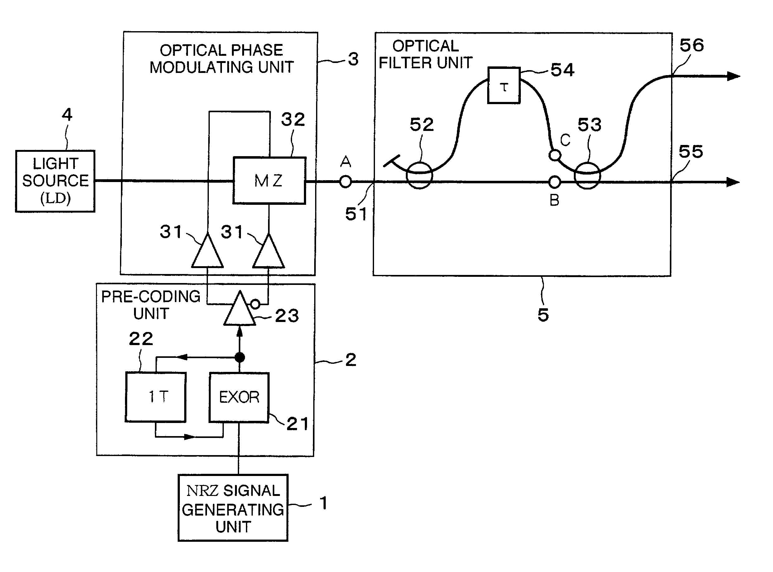
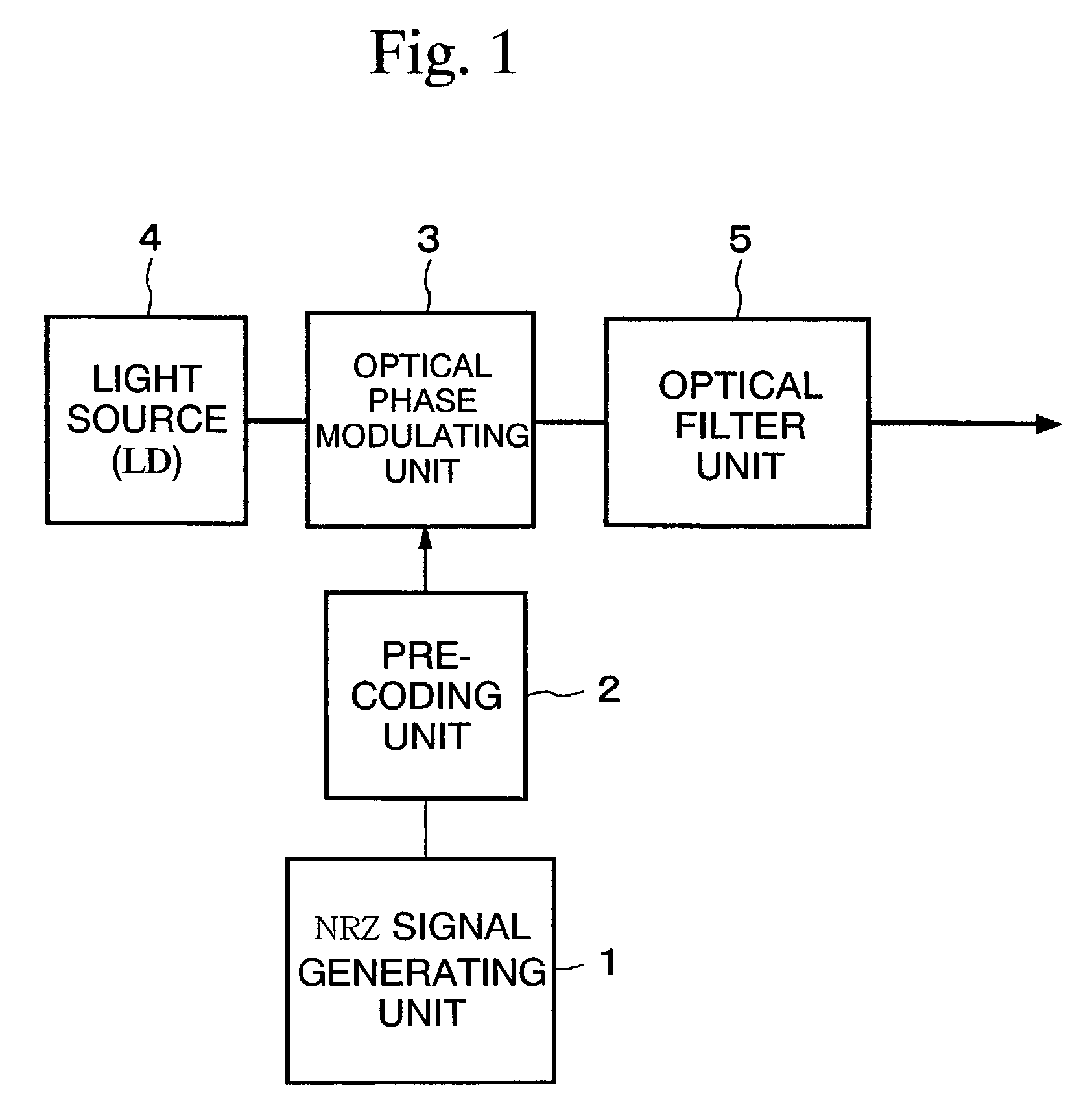
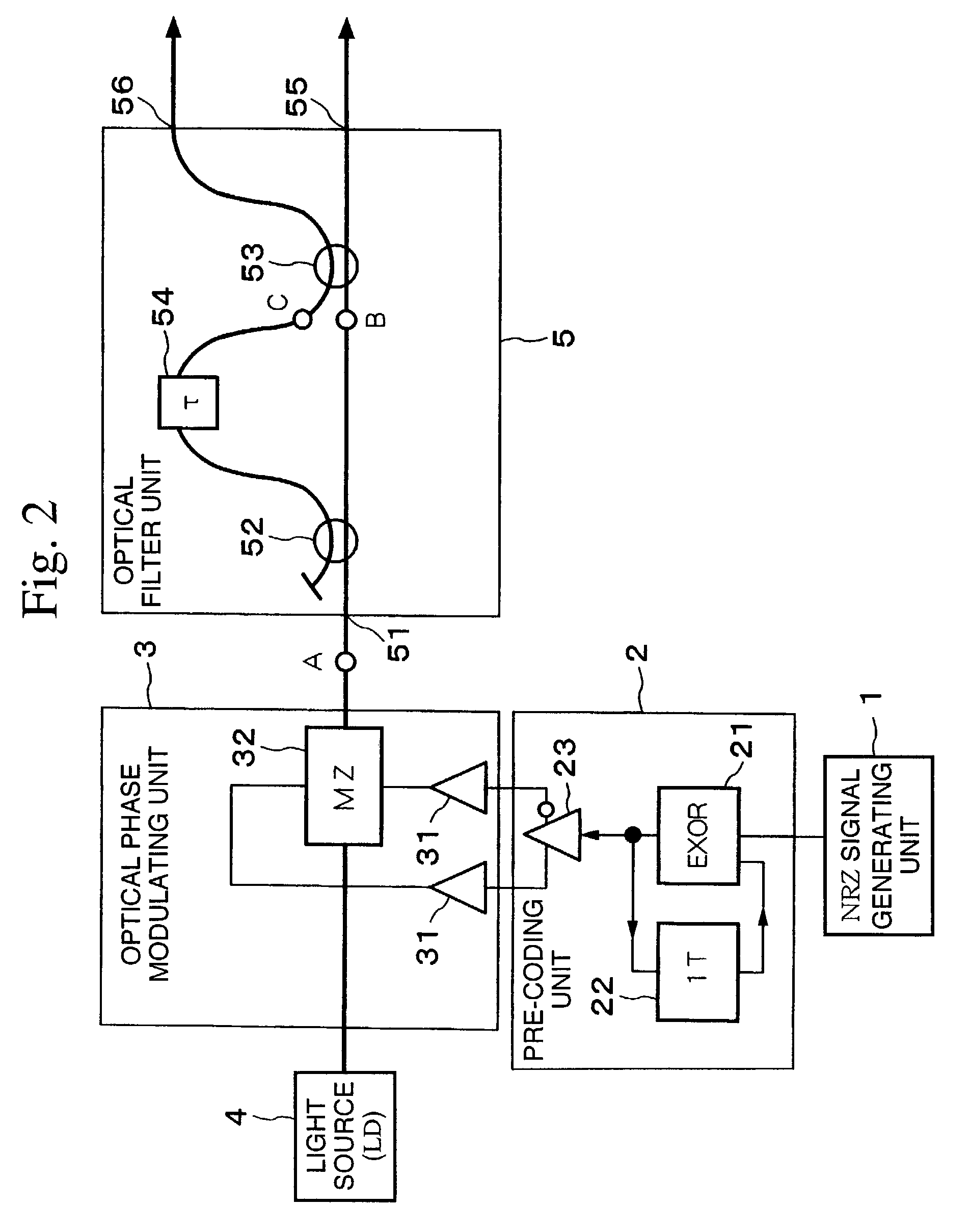
[0091]FIG. 1 is a block diagram showing an embodiment of the optical transmitter according to the present invention. In FIG. 1, the binary NRZ electrical signal output from the NRZ signal generating unit 1 is input into the pre-coding unit 2. The pre-coding unit 2 carries out signal processing so that the optical signal output from the optical transmitter matches the input NRZ signal. The differential pre-coded NRZ signal generated by the pre-coding unit 2 is amplified as necessary, and input into the optical phase modulating unit 3.

[0092]The single longitudinal mode CW optical signal emitted by the light source 4 (LD: a laser diode) is appropriately phase modulated by the optical phase modulating unit 3, and subsequently input into the optical ...


PUM


Abstract

The present invention suppresses to a minimum the degradation of the transmission quality caused by chromatic dispersion characteristic of an optical transmission medium, and the interplay between the chromatic dispersion and non-linear optical effects in dense WDM transport systems. A baseband input data signal is pre-coded in advance by a pre-coding unit, phase modulation is carried out using a pre-coded signal by the optical phase modulating unit, and the phase modulated optical signal is converted to an RZ intensity modulated signal by the optical filter unit that performs phase-shift-keying to amplitude-shift-keying conversion. For example, an optical phase modulating unit generates an encoded DPSK phase modulated signal using a differential phase shirt keying (DPSK) format, and a phase modulated signal is converted to an RZ intensity modulated signal by the optical filter unit disposed downstream of the optical phase modulating unit.

Description

BACKGROUND OF THE INVENTION[0001]1. Field of the Invention[0002]The present invention relates to an optical transmitter and an optical transmission system that can minimize the deterioration in the transmission quality due to the chromatic dispersion of an optical transmission medium such as an optical fiber, or due to the interaction between the chromatic dispersion and nonlinear optical effects.[0003]This application is based on patent application No. 2001-199467 filed in Japan, the contents of which are incorporated herein by reference.[0004]2. Background Art[0005]An RZ (return-to-zero) optical intensity modulation format used along with phase modulation has been proposed having the object of minimizing the deterioration in the transmission quality due to the chromatic dispersion of an optical transmission medium such as an optical fiber, or due to the interaction between the chromatic dispersion and nonlinear optical effects.[0006]For example, a citation 1, Y. Miyamoto et al. “D...

Claims


Application Information

Patent Timeline
IPC IPC(8): H04B10/12H04B10/2507G02F1/01H04B10/2513H04B10/516H04B10/548H04B10/556H04B10/588H04B10/61
CPCH04B10/5051H04B10/5055H04B10/516H04B10/5162H04B10/5561H04B10/677H04J14/0246H04B2210/517H04J14/0227H04J14/0279
Inventor MIYAMOTO, YUTAKAHIRANO, AKIRAKUWAHARA, SHOICHIROTOMIZAWA, MASAHITO
Owner NIPPON TELEGRAPH & TELEPHONE CORP
Why Eureka
Try Eureka