Control device, control method, control unit, and engine control unit
- Summary
- Abstract
- Description
- Claims
- Application Information
AI Technical Summary
Benefits of technology
Problems solved by technology
Method used
Image

Examples
first embodiment
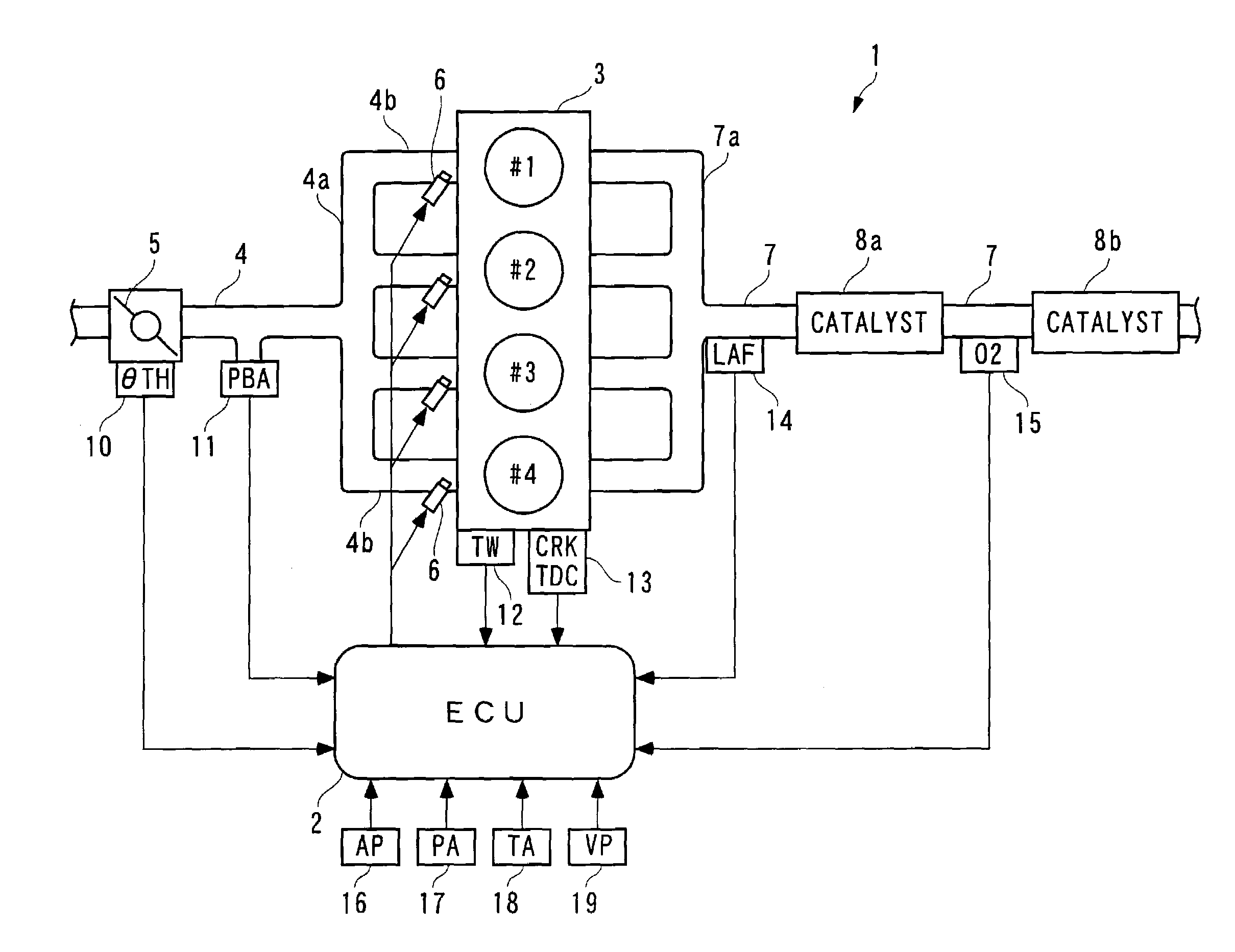
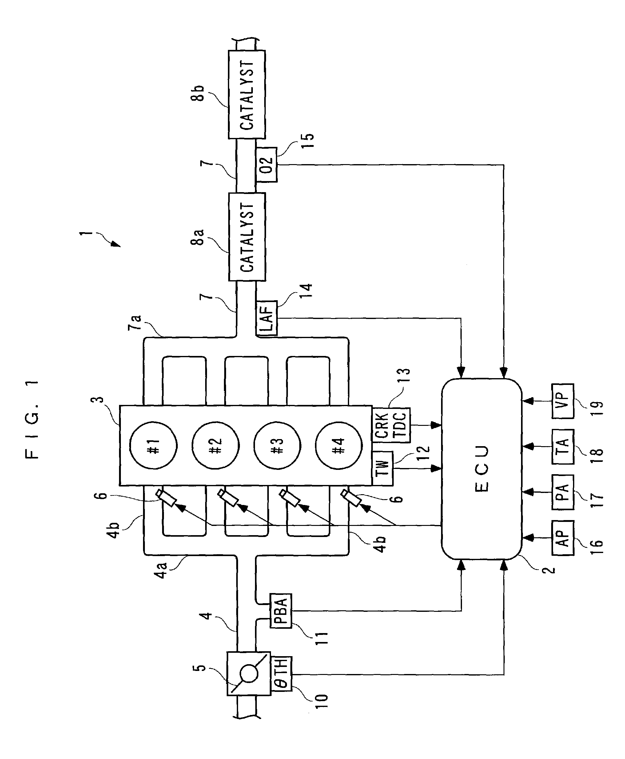
[0255]The invention will now be described in detail with reference to drawings showing preferred embodiments thereof. In these embodiments, a control device (control method, control unit, engine control unit) according to the invention is configured to control the air-fuel ratio of a mixture supplied to an internal combustion engine. Referring first to FIG. 1, there is schematically shown the arrangement of a control device 1 according to the invention and an internal combustion engine 3 to which the control device 1 is applied. As shown in the figure, the control device 1 includes an ECU 2 which controls the air-fuel ratio of an air-fuel mixture supplied to the internal combustion engine (hereinafter simply referred to as “the engine”) 3, as described hereinafter, according to operating conditions of the engine 3.
[0256]The engine 3 is an inline four-cylinder gasoline engine installed on an automotive vehicle, not shown, and has first to fourth cylinders #1 to #4. In the vicinity of...
tenth embodiment
[0507]Next, description will be given of a control device according to a Similarly to the FIG. 39 example, the present control device 1 is applied to an engine 3 provided with no LAF sensor 14, and having an O2 sensor 15 arranged at a location downstream of a second catalytic device 8b. Therefore, as shown in FIG. 44, in this control device 1, a sampled value of the output Vout from the O2 sensor 15 and a decimation value DKCMD′ of the target air-fuel ratio are used for calculation of the predicted value PREVO2 by a state predictor 22 and identification of the model parameters a1, a2, b1 by an onboard identifier 23.
[0508]Further, in a predictive algorithm used by the state predictor 22, a formula for calculating the predicted value PREVO2 is defined by an equation (76) shown below, based on the controlled object model expressed by the equation (60). On the other hand, an identification algorithm used by the onboard identifier 23 is expressed by equations (77) to (84) shown below. A...
ninth embodiment
[0512]According to the above control device 1, the same advantageous effects as provided by the control device 1 of the ninth embodiment can be obtained. In addition, since the control system 1 of the present embodiment requires no LAF sensor 14, it is possible to reduce manufacturing costs.
[0513]Further, in the control system 1 of the tenth embodiment, similarly to the control device 1 of the ninth embodiment, the decimation filters 40 may be replaced e.g. by samplers capable of sampling the target air-fuel ratio KCMD at the sampling period of ΔTsk, and the SDM controller 29 or the DM controller 30 may be used in place of the DSM controller 24.
[0514]Although in each of the above embodiments, the control device of the invention is used to control the air-fuel ratio in the internal combustion engine 3, this is not limitative, but the invention can be widely applied to control devices for controlling other controlled objects. Further, the ADSM controller 20 and the PRISM controller 21...
PUM
 Abstract
Description
Claims
Application Information
 - R&D
- Intellectual Property
- Life Sciences
- Materials
- Tech Scout
- Unparalleled Data Quality
- Higher Quality Content
- 60% Fewer Hallucinations
Browse by: Latest US Patents, China's latest patents, Technical Efficacy Thesaurus, Application Domain, Technology Topic, Popular Technical Reports.
© 2025 PatSnap. All rights reserved.Legal|Privacy policy|Modern Slavery Act Transparency Statement|Sitemap|About US| Contact US: help@patsnap.com